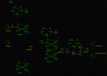
Ken , I have made a test with the circuit of post #1370 that consist in feeding the input with 3 current sources of 10000khz 10005khz and 10002khz. (picture 1 and 2)
Sergio,
Interesting results. Agreed, it appears the test circuit having the 2n2 output capacitor indicates that IM products were not only being produced by the expected upper sideband frequencies, but also by the intermodulation of those upper frequencies with each other. I must admit, however, that it's not obvious to me why a post amplification filter should reduce either the in band products stemming either from the intermodulated input frequencies, or from subsequent intermodulation of the upper sideband frequencies with each other.
Last edited:
How about something like this for a Sen floating power supply?
Switch A and B on and off alternately at 10Hz-100Hz with a gap of 1ms where they are both off to ensure the output supply is never connected to the input.
With 100Hz switching, could maybe reduce the big caps to make it smaller and even cheaper.
Would it work? Would it buzz?
Switch A and B on and off alternately at 10Hz-100Hz with a gap of 1ms where they are both off to ensure the output supply is never connected to the input.
With 100Hz switching, could maybe reduce the big caps to make it smaller and even cheaper.
Would it work? Would it buzz?
Attachments
Hallo,
I have a question about matching the jfets for a SEN V18.
In an earlier post, NicMac showed his matched jfets, which had an overall variation of about 0.2 mA.
I have some jfets here which vary from 22.0 to 23.4 mA, so 1.4 mA overall.
I have arranged them in the following order:
1a
22,00 Q1
22,02 Q3
22,02 Q4
22,04 Q2
1b
22,04 Q1
22,08 Q3
22,11 Q4
22,28 Q2
2a
22,35 Q1
22,40 Q3
22,56 Q4
22,58 Q2
2b
22,61 Q1
22,89 Q3
23,21 Q4
23,43 Q2
Overall I get quite good matching for each quad, but quad 1a does differ quite a lot from quad 2b. Does this influence the output characteristics or does offset, level, etc. only depend on the matching "within" each quad?
Thank you
I'm at the same place as you Kumori, but i do have even a little bigger difference between them all.
My guess is - since all upper fets are parallel to eachother and the same with the lower ones, and everything is connected together in "center" (input) i would think that the most important thing is to match the total idss of lower/upper as close as possible - and try to keep 1a/1b total idss as close as you can. At the same time it would be best if both channels also would be pretty much equal.
So my quess is that instead of keeping the Q1/Q3, Q2/Q4 matching as close as possible, you should look at keeping Q1+Q2 = Q3+Q4.
The Q1/Q3 matching i think is more important on the CEN.
Patrick could maybe clear this up, since this is just my guess of how it would work best.
So my quess is that instead of keeping the Q1/Q3, Q2/Q4 matching as close as possible, you should look at keeping Q1+Q2 = Q3+Q4.
The Q1/Q3 matching i think is more important on the CEN.
Patrick could maybe clear this up, since this is just my guess of how it would work best.
Well, I "matched" my FETs via excel-sheet in the following way:
I sorted them by measured IDSS and grouped them in subsequent quads.
Each quad was labeled in the following order: Q1, Q3, Q4, Q2.
This results in Q1/Q3 and Q2/Q4 being as close together as possible and because Q1 is the smallest and Q2 the largest value, Q1+Q2 and the two middle ones (Q3+Q4) are of -similiar- value. This works especially well for 1a and 2a, and on 1b and 2b I only get about 0.1 mA deviation.
My thinking was, that the absolute Idss of each quad only is the maximum current swing possible. So the difference in Idss values of the individual quad should have no effect on the performance when each of them is large enough.
kumori, we are probably talking about very small differences either way - but of course you want to maximise the performance of the circuit.
Anyway, this is how each of my hexa-sets measures:
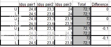
But the current is not only about swing - higher current also lower the input impedance of the circuit - So that can give difference in sound, albeit very small, since it's no big differences in total current.
EDIT: After some more moving FETs around, i get +-0 on each channel. without "to" big difference between the upper/lower fets. all channels between 71,9 - 72,3mA
Anyway, this is how each of my hexa-sets measures:
But the current is not only about swing - higher current also lower the input impedance of the circuit - So that can give difference in sound, albeit very small, since it's no big differences in total current.
EDIT: After some more moving FETs around, i get +-0 on each channel. without "to" big difference between the upper/lower fets. all channels between 71,9 - 72,3mA
Last edited:
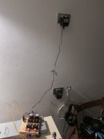
buzz when using batteries
Hi
I managed to set up Sen
I use NiMh batteries
the sound Is better than old I/V but I hear buzz
what may be source for buzz - longer series wires between 3 x batterie stacks (about 10 cm) or relatively small filter capacitance of 4700uF after batteries
Hi
I managed to set up Sen
I use NiMh batteries
the sound Is better than old I/V but I hear buzz
what may be source for buzz - longer series wires between 3 x batterie stacks (about 10 cm) or relatively small filter capacitance of 4700uF after batteries
kumori, we are probably talking about very small differences either way - but of course you want to maximise the performance of the circuit.
Anyway, this is how each of my hexa-sets measures:
But the current is not only about swing - higher current also lower the input impedance of the circuit - So that can give difference in sound, albeit very small, since it's no big differences in total current.
EDIT: After some more moving FETs around, i get +-0 on each channel. without "to" big difference between the upper/lower fets. all channels between 71,9 - 72,3mA
Well your matching method also looks well. I guess your right, probably the differences are quite small in the end...
Difference between Q1+Q2 & Q3+Q4 determines DC offset at the input.
Difference between Q1/Q3 and Q2/Q4 determines thermal tracking.
Patrick
Patrick, if I may ask: Which effects does offset at the inputs generate? Doesn´t the current offset at the input directly reflect in voltage offset at the output?
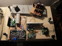
Hello Patrick,
my SEN proto works fantastic with no noise at all.
Thanks a lot.
Guglielmo
You have it connected single ended or only one channel is done?
Your build does not justify Italian design

But I know it sounds gooood...
Thanks to Patrick - of course
That is interesting Guglielmo. I was thinking that a transformer with secondary away from primary was mandatory, like in a R-core transformer, to keep the line noises from getting in to the signal.
can you open the case of the transformer ?, just to see if it has separate primary and secondary, sometimes even a cheap transformer has them in separate bobbins. Thanks.
can you open the case of the transformer ?, just to see if it has separate primary and secondary, sometimes even a cheap transformer has them in separate bobbins. Thanks.
Last edited:
This is not a R-core transformer but it has a bobbin for primary separate from the secondary, so it has low interwinding capacitance and is very cheap.
FP24-500 Triad Magnetics | Mouser
FP24-500 Triad Magnetics | Mouser
Well, now i really need to order a custom r-core 4 x 0-18V secondary ~200-250mA, to try with - just waiting for the to92 coolers right now, and the possibly the transformer.
how about 4 x 9Vac
you can always do a 2 x 18Vac
If you can arrange It there will be much people Involved and price will be lower
- Home
- Source & Line
- Digital Line Level
- Zen -> Cen -> Sen, evolution of a minimalistic IV Converter