Member
Joined 2009
Paid Member
I agree - the point is, it's not so simple to design a protection system as you have done, and one that covers all the aspects and there aren't really many alternatives either - as you point out they have their own flaws.
I think its going to be important to adequately test the protection you have designed, with a real speaker load - do you have some old drive units that can be sacrificed ?
Recently I tested a dc protection circuit (not my design I should point out !) and thought it working fine, but I tested only with +ve dc. It didn't work with -Ve dc. Reminding me that I have to test things properly. I get lazy with DIY
My own amp is using nicely the same idea since decades. Tested on all situations, including hundreds of short circuits on Loudspeaker's lines, at the time i demonstrated this idea, trying to sell-it. Still well and alive, living in my home.I think its going to be important to adequately test the protection you have designed, with a real speaker load - do you have some old drive units that can be sacrificed ?
The company i was in touch with at this time, was more interested by my amp itself than the protection. I gave-it up, sometimes, i can't afford stupidity.
Last edited:
Some little errors and a little improvement, i will post later. (An indicator for over temp).VERSION 1.03 parts renumbered
Thanks a lot, it is very nice, you make nice drawings.
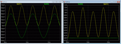
Now, about + & - protection: there is the signal (yellow) after rectification of the original error signal from the amp (green).
I still have a little problem with it as the symmetry is perfect with 28.7K in feedback of U3 (left image), but vary a little with it. Still searching for the solution for it. Can be solved adding an other OPA for varying the gain, that i don't want.
This is due because the - input of U3 has an impedance with vary a little with gain (P3 value).
Not a real issue, it plays on <0.2 v of offset.
Attachments
OK so we are dealing with error signals (as I come late to the thread) for two distinct amp channels? Pardon my ignorance.Now, about + & - protection: there is the signal (yellow) after rectification of the original error signal from the amp (green).
I still have a little problem with it as the symmetry is perfect with 28.7K in feedback of U3 (left image), but vary a little with it. Still searching for the solution for it. Can be solved adding an other OPA for varying the gain, that i don't want.
This is due because the - input of U3 has an impedance with vary a little with gain (P3 value).
Not a real issue, it plays on <0.2 v of offset.
The Hafler protection circuit I use in my amp works very nicely. Yesterday, I was testing a new preamp construct and one of the input lead came off. I just pushed it with the finger which led to a ringing sound in the speaker. Immediately, the protection relay kicked in.
Gajanan Phadte
Gajanan Phadte
Indeed. Plus soft start etc...OK so we are dealing with error signals (as I come late to the thread) for two distinct amp channels? Pardon my ignorance.
Problem solved, bcarso (nice to see-you here). I had changed my mind for comparators: no way to get something clean with diodes, i wanted to save parts, it was stupid.
Now everything is rock solid.
I'm just afraid coolet will kill-me
I'm very happy to know you're happy.The Hafler protection circuit I use in my amp works very nicely.
i'm waitingNow everything is rock solid.
I'm just afraid coolet will kill-me
Member
Joined 2009
Paid Member
The Hafler protection circuit I use in my amp works very nicely. Yesterday, I was testing a new preamp construct and one of the input lead came off. I just pushed it with the finger which led to a ringing sound in the speaker. Immediately, the protection relay kicked in.
Gajanan Phadte
This sounds interesting, perhaps something to learn, whether it is good, bad doesn't matter - can you post a schematic ?
I found this: Transistor amplifier protective circuit
but it doesn't look like a very comprehensive protection
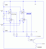
here is the principle of the last version. As rectifier diodes where not linear with various signal levels, there was a small inaccuracy that left me unsatisfied.
Here the principle of this new version, ROCK stable.
The two channels are not mixed any more, each one is monitored separately.
The total final schematic will use the first two previous stages, two differentiators, making the difference between input and output signals of your amp.
They output two error signal which are amplified. Then, the peaks those error signals are compared to 2 reference levels, making a gap, for both positive and negative signals, into comparators. When they reach one of the two thresholds, the output of the comparators goes down (they are up in normal state) the protection fires.
This signal is applied to the tempo previously used during starting process (5 S.) in order the speakers stay disconnected during 5seconds, even id the failure was just a millisecond, to avoid repetitive toggling of the protection.
Here the modified schematic. The number of part has been reduced a lot, and the quad comparator is very cheap.
Final schematic follows very soon.
Attachments
With open-collector comparators like the 139 you don't need the diodes.here is the principle of the last version. As rectifier diodes where not linear with various signal levels, there was a small inaccuracy that left me unsatisfied.
Here the principle of this new version, ROCK stable.
The two channels are not mixed any more, each one is monitored separately.
The total final schematic will use the first two previous stages, two differentiators, making the difference between input and output signals of your amp.
They output two error signal which are amplified. Then, the peaks those error signals are compared to 2 reference levels, making a gap, for both positive and negative signals, into comparators. When they reach one of the two thresholds, the output of the comparators goes down (they are up in normal state) the protection fires.
This signal is applied to the tempo previously used during starting process (5 S.) in order the speakers stay disconnected during 5seconds, even id the failure was just a millisecond, to avoid repetitive toggling of the protection.
Here the modified schematic. The number of part has been reduced a lot, and the quad comparator is very cheap.
Final schematic follows very soon.
You are right. I take too many precautions. I remove them.With open-collector comparators like the 139 you don't need the diodes.
Overall performance is amazing: Every error over the threshold witch persist more than 35µs (30µs in case of hot rail) will fire the protection in 6µs (MOS relay) for 5 seconds after the error had stopped.
I doubt any other amp protection in the world is that fast !
If one of your power transistor burn in short circuit, you will not even hear-it. (half of a 15Hz sin).
Rolls Royce.
Last edited:
Member
Joined 2009
Paid Member
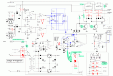
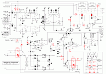
UAPC version 2
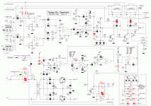
As explained, the OPAs U1 & U2 makes the difference between input and ouput of the amp.
The two error signals are amplified by U3 & U4.
Then peaks are compared to two symmetrical + & - references set by the 10K-20K-10K bridge.
The outputs of this comparators (open collector) turn low when fired. This turn on the transistor T4. +12v iss sended in the - input of K3 via a diode. K3 turn low, this fired the protection via D10. In the same time, it force the base to stay low via the blue diode, during the time the capacitor is charged: this make an hysteresis to ensure the protection stay low during enough time even if the pulse was very short.
When the error cease, C12 discharge slowly (5 seconds) via R29+R28, assuming K2 (end of soft start) is low.
The same K3 assure the 5 second delay to connect loudspeakers during the starting session.
Too, an indicator for overload temp has been added. It can be a 5V 20ma blinking diode (paralleled with a 5V zener) .
That's all, folks.
For coolet, a resistance R? has been added. This is to can use an other quad comparators for the delays instead of the original OPA, chosen to simplify the BOM. It will save money by the same time.
Attachments
Last edited:
- Status
- This old topic is closed. If you want to reopen this topic, contact a moderator using the "Report Post" button.
- Home
- Amplifiers
- Solid State
- An ultimate amp protection circuit ?
