Sadly thats too low power for meThe data sheet shows the minimum voltage for the TDA2050 to be 9 volts and the TDA2040 to be 5 volts, however, everyone I tried came on at 3 volts.
 would want at least 40w
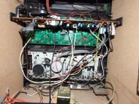
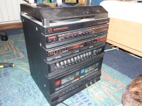
Help me identify and fix this piece of crap that is quite sentimental to my mom which upon powerup does nothing but hiss,it also has remot control,and an obvious defect is that is just switching the power to the amp not the power to the transformer,otherwise the speakers are cheap and i will ose some diferent ones,and i will also usee a diferent chip amp,the tda 1517,but it died and i dont know the supply voltage on that amp
Attachments

![DSCF2909[1].JPG](/community/data/attachments/291/291969-3295503f9d1f9f59773a075a0b96ad55.jpg)
Help me identify and fix this piece of crap that is quite sentimental to my mom which upon powerup does nothing but hiss,it also has remot control,and an obvious defect is that is just switching the power to the amp not the power to the transformer,otherwise the speakers are cheap and i will ose some diferent ones,and i will also usee a diferent chip amp,the tda 1517,but it died and i dont know the supply voltage on that amp
Hi these units are not complicated but normally have dedicated ICs that may be difficult to trace - I'd get the multimeter fixed and find out whats happening to the internal power supplies. As always a schematic for the unit would help greatly!
Just built an usb powered tda 2822m and when i hook it up to my test radio along with the music i hear a 50hz loud buzz i once plugged it in my computer and there also was a lot of buzz
Which circuit did you follow?
Why is no one answering,why
- been busy helping others too!!
Thanks for stopping by,the schematic is from datashee without zobel but i could not hear any high frequency oscilation while it was workingWhich circuit did you follow?
Thanks for stopping by,the schematic is from datashee without zobel but i could not hear any high frequency oscilation while it was working
It is still a good idea, especially with "chip amps" to leave the specified Zobel network in. This is because like in the old days, the easiest way to get a power output stage in a chip is using NPN transistors only. You can see this if you look at P. 2 of the datasheet. The bottom transistor is working with it's collector going to the speaker. This is inherently problematic and can result in instability with open circuit or high impedance loads. The Zobel network helps keep things under control - so leave it out at your peril!!
BTW you are unlikely to *hear* the oscillation - it's clattering away at way beyond human hearing, - perhaps at a Mhz or so!! The normal giveaway (without resorting to an oscilloscope) is a very hot chip, even when it's doing nothing...
Last edited:
i have used 220uf on supply and havent left the pins floating i have them conected to ground trough 100 uf caps as in schematic,it previousely worked,but now it dosent workummmm (hahaha) its usually either the supply rail needs a 10uF (maybe more say 100uF) capacitor accross it ir you've left the "unused" opamp input pins floating....
i have used 220uf on supply and havent left the pins floating i have them conected to ground trough 100 uf caps as in schematic,it previousely worked,but now it dosent work
I think you need to look again at your wires and soldering - it feels like you've connected something and its disconnected since!
Since when in use on a computer soundcard AND its USB port the power is grounded in two places you could try (completely disconnected from computer of course!):
Disconnect the negative connections of C1 and C2 (fig. 1 of datasheet) from the board.
Join the two negative terminals of the capacitors together but not to 0V on the board.
Disconnect the screen of your left AND right inputs ( I presume this is coming from your soundcard line output) from the board and join it to the new junction of C1 and C2.
See if that improves matters!
Last edited:
- Status
- This old topic is closed. If you want to reopen this topic, contact a moderator using the "Report Post" button.
- Home
- Amplifiers
- Chip Amps
- lm1875 fizzing away probelm