Hi Frank,
thank you for update on depron. good to know.
The thing about surround is that while Cms doesn't have a contribution to high frequency response, Mms does. You have to take in account the fact that at least 1/3 of surround mass is added to Mms along with cone mass, voicecoil mass, glue mass and 1/3 of spider mass.
Also, you will need to experiment to see if it provide a proper cone termination and this is the hardest part because you need a good mechanical impedance matching. With a good match the effects of radial cone breakup modes should be minimized.
With my project i am sourcing aluminum for my frame, try a couple more voicecoils and making a setup for distortion measurements.
Hi Frank,
thank you for update on depron. good to know.
The thing about surround is that while Cms doesn't have a contribution to high frequency response, Mms does. You have to take in account the fact that at least 1/3 of surround mass is added to Mms along with cone mass, voicecoil mass, glue mass and 1/3 of spider mass.
Thanks Hentai, I did not know that, it is always nice to learn new stuff. I have be looking all over the internet for a "How to make your own unit" but I don't think there is a lot of info on the topic.
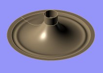
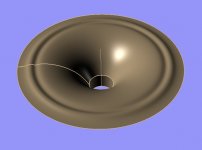
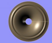
Here is a thought... To eliminate traditions between the voice coil and membrane and from the membrane and the surroundings you could make a combined unit like show below. This way you can make the hole thing extreme light, I am guessing about 3-4 g without the copper. Also you don't need to glue the hole thing together with more or less know glue spec's.
I know you don't have a lot of Xmax but this is no problem for me, as they will be cut at around 80Hz. Please coment.
Attachments

Frank, how is that any different from what we see today?Hi Frank,
thank you for update on depron. good to know.
The thing about surround is that while Cms doesn't have a contribution to high frequency response, Mms does. You have to take in account the fact that at least 1/3 of surround mass is added to Mms along with cone mass, voicecoil mass, glue mass and 1/3 of spider mass.
Thanks Hentai, I did not know that, it is always nice to learn new stuff. I have be looking all over the internet for a "How to make your own unit" but I don't think there is a lot of info on the topic.
Here is a thought... To eliminate traditions between the voice coil and membrane and from the membrane and the surroundings you could make a combined unit like show below. This way you can make the hole thing extreme light, I am guessing about 3-4 g without the copper. Also you don't need to glue the hole thing together with more or less know glue spec's.
I know you don't have a lot of Xmax but this is no problem for me, as they will be cut at around 80Hz. Please coment.
Well i think it is a great idea, making the former as an extension of the cone. I would assume it would be difficult as a DIY procedure tho?
For a home system, high efficiency full range, i dont think we need to worry about the former handling large temperatures. I just needs to be thin enough and ridig enough.
Great idea Frank, do you think it can be done in diy conditions?
For a home system, high efficiency full range, i dont think we need to worry about the former handling large temperatures. I just needs to be thin enough and ridig enough.
Great idea Frank, do you think it can be done in diy conditions?
Agree, very neat and economical thinking.
Possible to vacuum form as well. However the vertical wall of the coil former would be very thin compared to the more horizontal parts and the sharp angles will cause high stress regions and therefore need to be much more rounded - all stuff that is fairly easily addressed when designing the pattern.
Possible to vacuum form as well. However the vertical wall of the coil former would be very thin compared to the more horizontal parts and the sharp angles will cause high stress regions and therefore need to be much more rounded - all stuff that is fairly easily addressed when designing the pattern.
454Casull,
I haven't seen any speaker build in this way, but if you have seen it please post a link. The moving parts, voice coil, membrane, surroundings and the spider are normally 4 separate parts that are glued together to form one unit.
Hentai and Johno,
Glad you liked to idea. I think it can be done by us DIY's but I wouldn’t use the vacuum forming technique....as Johno mentioned, the vertical walls will be to thin. The tricky part is to get the thing of the former. I would use glass or carbon fibre, at this point fibre glass sounds best but haven't tried carbon fibre yet. I don't know if you know this, but you can get epoxy glue for many purpose some can handle high temp. and you can get a variety of softer and harder types. You can also ad different additives to change it's properties.
I have used a lot of different types of epoxy over the years designing and building air planes, so this will be my first choice. Now I will get some material and tolls to make a former for this new one.
Take care.
I was thinking about carbon fiber as well at Magura's suggestion but I'm still not ready to give up on paper. Paper to me always been the best sounding cone material. Keep us posted on how things develop at your end Frank.
Meanwhile aluminum rods for the frame have arrived. Time to put them in the machines.

Meanwhile aluminum rods for the frame have arrived. Time to put them in the machines.
I did not see that everything was of the same piece.454Casull,
I haven't seen any speaker build in this way, but if you have seen it please post a link. The moving parts, voice coil, membrane, surroundings and the spider are normally 4 separate parts that are glued together to form one unit.
As long as all performance requirements are satisfied, it should work quite well. The surround needs to have a relatively low stiffness, with high self-centering and fatigue life, and customizable damping. The voice coil former needs to be round enough, strong enough, resistant to high temperatures, suitable for bonding to the coil.
Time to put them in the machines.
What machines do you use?
(Just in the middle of installation of my de Valliere lathe.)
Best wishes
David
Hi to all
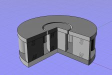
Here is another thought, see the picture below. I have replaced the centrer pole with a magnet, this should work like stacking magnets and increase the flux and help to saturate the iron . Please comment.
Because of the magnets lower permeability than irons the flux in the gap will be less than if it was iron and maybe that will be not the the only one negative effect.
Hi guys,
Frank my first thought was saturation of the pole pieces, stefanyovev has a point tho. If i can find the time this weekend i will run it through FEMM.
David saw your post and i took some pictures of the PUMA 400


Also automated drilling machine and the good old lathe, working hard.


Would love to see a pic of your Valliere when its all setup.
Baldin Thank you for your comment. Do you have a link to that company? i cannot see it in your post.
Frank my first thought was saturation of the pole pieces, stefanyovev has a point tho. If i can find the time this weekend i will run it through FEMM.
David saw your post and i took some pictures of the PUMA 400
Also automated drilling machine and the good old lathe, working hard.
Would love to see a pic of your Valliere when its all setup.
Baldin Thank you for your comment. Do you have a link to that company? i cannot see it in your post.
Stefanyovev. Are sure that magnets are less conductive than iron, this dose not sound logical to me. And it dose not correlate to my findings on the internet, see these two links.... Maybe I misunderstood some thing.
Magnetic properties of materials
Magnetic properties of materials
Hentai. Man that is one nice workshop you have, I would love to have that kind of machinery. It would be great if you can do a simulation, I am having some trouble in using the program.
Take care
Magnetic properties of materials
Magnetic properties of materials
Hentai. Man that is one nice workshop you have, I would love to have that kind of machinery. It would be great if you can do a simulation, I am having some trouble in using the program.
Take care
Yes, of course.Are sure that magnets are less conductive than iron,
That's why magnets are used to "generate" the magnetic field, at a lower flux density, and soft iron is used to *guide and concentrate" it, in the desired gap.
By the way, a magnet used as a polepiece, besides being a *terrible* material for that, will have the added disadvantage of *opposing* the main magnet flux because it will be magnetized the wrong way, at least in any "normal" magnetizer.
That's why magnets are used to "generate" the magnetic field, at a lower flux density, and soft iron is used to *guide and concentrate" it, in the desired gap.
This depends on the permanent magnet material and is partly a matter of perspective.
It helps to concentrate the flux for low flux density sources like ferrite.
For Neodymium the main reason to use soft iron is the difficulty and cost to produce a magnet with a radial field.
An axial flux magnet and steel pole piece is just cheaper.
The old Aura 18 NRT sub-woofer did use a Neo. Radial field magnet but was rather expensive and had consequently limited production.
Earlier in this thread "Linesource" showed a simulation with more than 2 tesla field where the elimination of the pole-piece was actually the key. Not a practical structure as shown but of interest. Pity he never followed up.
Best wishes
David
Here are the Femm results:
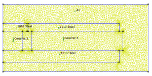
For ceramic 5 PMs, 8mm gap 1010 steel:
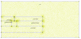
Structure (showing polarity of PMs):

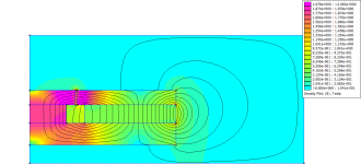
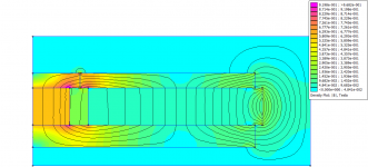
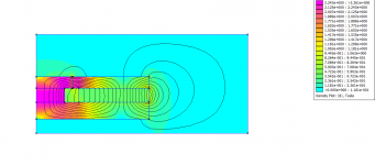
Central pole made of PM, magnetic lines:

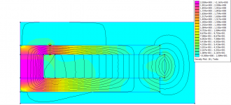
Central pole made of 1010 steel, magnetic lines:

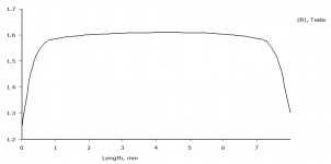
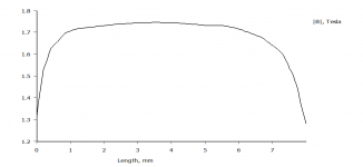
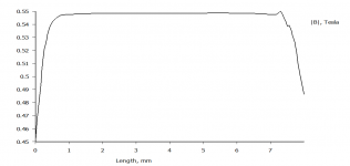
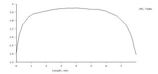
Central pole made of PM, B value across gap:

Central pole made of 1010 steel, B value across gap:

For NdFeB40 PMs, 8mm gap 1010 steel:
Structure (showing polarity of PMs):

Central pole made of PM, magnetic lines:

Central pole made of 1010 steel, magnetic lines:

Central pole made of PM, B value across gap:

Central pole made of 1010 steel, B value across gap:

Effects are less noticeable with Neo PMs but still steel wins
For ceramic 5 PMs, 8mm gap 1010 steel:
Structure (showing polarity of PMs):
Central pole made of PM, magnetic lines:
Central pole made of 1010 steel, magnetic lines:
Central pole made of PM, B value across gap:
Central pole made of 1010 steel, B value across gap:
For NdFeB40 PMs, 8mm gap 1010 steel:
Structure (showing polarity of PMs):
Central pole made of PM, magnetic lines:
Central pole made of 1010 steel, magnetic lines:
Central pole made of PM, B value across gap:
Central pole made of 1010 steel, B value across gap:
Effects are less noticeable with Neo PMs but still steel wins
Attachments
-
 Steel pole piece lines.png56 KB · Views: 62
 -
 Steel pole piece B.png14.7 KB · Views: 58
 -
 neo vs steel structure.png116.3 KB · Views: 57
 -
 Neo pole piece lines.png54.6 KB · Views: 50
 -
 Neo pole piece B.png17.5 KB · Views: 52
 -
 Ceramic 5 pole piece lines.png56.6 KB · Views: 59
 -
 Ceramic 5 pole piece B.png18.6 KB · Views: 64
 -
 1010 pole piece lines.png45.2 KB · Views: 67
 -
 1010 pole piece B.png17.3 KB · Views: 54
 -
 structure.png49.6 KB · Views: 65
Thanks for simulating and posting.
And let me repeat something many don't notice:
you simulated the center piece magnetized the opposite way (geometrically) to the main external ring magnet, meaning: if, say, the outer ring has North up, you simulated the magnetic material "polepiece" North down .... which only happens in simulations
Hey!! , in Simulation World you can simulate *anything*, even if it's technically impossible
Notice I didn't say "physically" impossible.
But I stick to real world speaker production technology.
But if such speaker is magnetized in any commercially available magnetizer, *everything* within the magnetizer coil or gap will be pushed the same way, by definition.
Say, everybody "North up" , including the pole piece and any other magnetic element of that structure.
So? ........... what happens after you cut current off?
The soft iron (SAE1010) polepiece will "forget" that induced magnetization and happily take whatever the hard magnetic material tells it to (Ferrite/Alnico/Samarium/etc.).
If you use a hard magnetic material for the polepiece that will not happen and it will fight the main magnet.
In practice, it will be worse than even not using a polepiece at all
I have built my own magnetizers and use them everyday in speaker production.
Of course , I had to design them from the ground up.
No real data on Internet even today .... and we are talking mid 70's , not even Internet !!!
And one point to consider was that beyond fully magnetizing Ferrite, I had also to saturate the polepiece, or it would act as a very real magnetic short sucking lineforces from the Ferrite.
That's why magnetizers are such power guzzlers.
My "small" one at the shop, good for 105mm magnets, needs over 40A @ 220 Volts monophasic, do the Math, over 8 KW.
In fact, when magnetizing, I go "outside" and clamp it straight to the 220V Power Company line, to avoid resetting PCs , etc, at home.
The "Mid" one, good for ~150mm magnets is at a friend's factory, because it needs 3x380V full wave rectified (equivalent to around 500V DC) @ 47 Amperes= over 20 KW.
Magnetizing pulses are short, but the line must be able to deliver.
I'm building a large one, good for 190 and 220 mm magnets (so I can clone EVM, JBL, etc.) but it will be capacitive discharge because , simply, I can't afford the special reinforced Power Line it will need.
So in a wayyou took the "easy" path
You just built a "dedicated magnetizer" and made it part of the speaker.
FWIW: together with some friends, I built a 30" speaker in the early 80's .... and had to use a field coil
An incredible technical achievement, a terrible financial disgrace.
We built 4 of them but never could sell any
Oh well.
So I'm following your project with the utmost attention, brings *many* bitter sweet memories.
- Home
- Loudspeakers
- Multi-Way
- Project Ryu - DIY Field Coil Loudspeaker