Hi
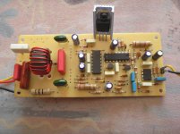
please share a very good quality picture from your amp
i want chek your amp parts and my amp too
maybe i have problem in filter zone. right ?
thanks
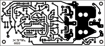
D200 HQ
Attachments
Hi IRsound,where can i find difference between this two topologies ? I really want to understand how they work...but i cant find a short and good article about this..if you don't mind , please give me some lessons.
UCD means universal class d, mainly all forum members says UCD is self oscillated type class d amp
IRAUDIO(D200 mile's) designs are Delta sigma self oscillated type class d amp this is the final version.
like Lm311,lm393 and lm319,they used both topology
(a) self osc. one
(b) carrier based one
Regards
MANOJ
Last edited:
Hi sir mile
1. 0.1 ohm 2w
2. 2n5401
3. 2n5401
4. tip31c
5. 3.3k ohm
6. 100 ohm
7. 100 ohm
8. 1k ohm 2w
9. 1k ohm 2w
10. 68k ohm
11. 1k ohm 1%
i was used this part insted your parts
i use T106-2 for filter too
my mosfets are IRFP250N
what can i do ?
An externally hosted image should be here but it was not working when we last tested it.
1. 0.1 ohm 2w
2. 2n5401
3. 2n5401
4. tip31c
5. 3.3k ohm
6. 100 ohm
7. 100 ohm
8. 1k ohm 2w
9. 1k ohm 2w
10. 68k ohm
11. 1k ohm 1%
i was used this part insted your parts
i use T106-2 for filter too
my mosfets are IRFP250N
what can i do ?
Last edited:
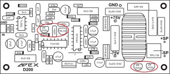
sorry but i can not read part number of you IC S .
10 is 10k resistor, not 68k, there is not 68k resistor on this amp only 6k8.
Use IRF640N and 47 ohm instead 100 ohm, ICs are TL081, 74HC00 and IR2110.
Regards
Sir Mile,
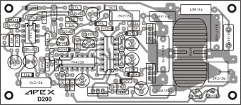
why is the orientation of the 2n5401 & 78L05 do not match in this given parts lay out...
My mistake (reverted pins), use orientation from first layout, and you can see orientation on picture in post #241.
My Amp not working
Hi Mile,
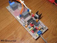
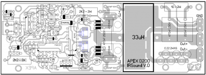
I design new board , because i want to change some footprints or change some capacitors to smd type...
after finishing assembly , i connect +/-44v supply and 1KHz sine wave from PC to input. but measured waves aren't familiar to me. i think my board have some problem..but i check it lots of times..i can't find it..
i attached measured waves , also a picture of my amp and layout. after extract Zip file , please read that notepad file.
please help me mile..
Regards,
IRSound
Hi Mile,
I design new board , because i want to change some footprints or change some capacitors to smd type...
after finishing assembly , i connect +/-44v supply and 1KHz sine wave from PC to input. but measured waves aren't familiar to me. i think my board have some problem..but i check it lots of times..i can't find it..
i attached measured waves , also a picture of my amp and layout. after extract Zip file , please read that notepad file.
please help me mile..
Regards,
IRSound
Attachments
Last edited:
My mistake (reverted pins), use orientation from first layout, and you can see orientation on picture in post #241.
OK sir thanks, missed that one..
Hi abetir,
Thanks , i've just checked them.
but their are correct , re check them carefully. because i change some component direction or their place.
1-that 10Kohm resistor is for start-up mute.value is correct.
2-input pin of 78L05 should connected to +12v and 100nf cap.it's correct.
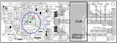
3-collector pin of 2n5401 connected to a 1K resistor. after resistor it should be connect to 4 places : 1-10pF cap 2-6K8 resistor 3-anode of 4148 4-pin 12 of 74HC00 , so all of them connected in correct point in my board.
Voltages are almost ok (+/-5v and +12v) , but that waves show something which i can't understand it.
Regards
Thanks , i've just checked them.
but their are correct , re check them carefully. because i change some component direction or their place.
1-that 10Kohm resistor is for start-up mute.value is correct.
2-input pin of 78L05 should connected to +12v and 100nf cap.it's correct.
3-collector pin of 2n5401 connected to a 1K resistor. after resistor it should be connect to 4 places : 1-10pF cap 2-6K8 resistor 3-anode of 4148 4-pin 12 of 74HC00 , so all of them connected in correct point in my board.
Voltages are almost ok (+/-5v and +12v) , but that waves show something which i can't understand it.
Regards
Last edited:
Hi Mile,
I design new board , because i want to change some footprints or change some capacitors to smd type...
after finishing assembly , i connect +/-44v supply and 1KHz sine wave from PC to input. but measured waves aren't familiar to me. i think my board have some problem..but i check it lots of times..i can't find it..
i attached measured waves , also a picture of my amp and layout. after extract Zip file , please read that notepad file.
please help me mile..
Regards,
IRSound
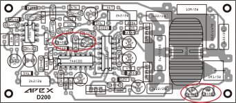
Please check this, i hope this can help.
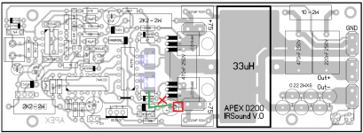
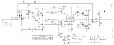
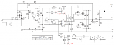
IR2110 (pin#2),100n, 10uf and 47uf must connected to ground of 78L05 transistor not in -75 rail.
Regards,
Attachments
Last edited:
Hi Wiljj ,
Thanks for helping..
- Pin 2 of 2110 should be connected to low side mosfet source pin (or -75v) like apex pcb. but there is just a small difference in routing.also ground pin of 78L05 should be connected to -75v rail. (like apex schematics via jumpers). so my board is correct in this ways.
does anyone knows anything about waves ? (which i attached them in previous page)
i also connect 33uh filter , i have 165khz sine wave with no input !!
Regards
Hi Wiljj ,
Thanks for helping..
- Pin 2 of 2110 should be connected to low side mosfet source pin (or -75v) like apex pcb. but there is just a small difference in routing.also ground pin of 78L05 should be connected to -75v rail. (like apex schematics via jumpers). so my board is correct in this ways.
does anyone knows anything about waves ? (which i attached them in previous page)
i also connect 33uh filter , i have 165khz sine wave with no input !!
Regards
You're right, i just notice lately when i compare the component guide vs. PCB that there some difference of tract routing after the PCB was posted, my mistake, pls. ignore my post.
All the best.
Wiljj78
,
Attachments
Hi Manoj,mackie SRM450 shematic shows one inverting buffer amp was provided in input. Without this your amp(D200 and others IRS900 etc.. ) out put is 180 degree out phase. Did you check this??
i attached a mixed schematic of previous pages..D200 schematic should be something like this , also it have some zener diode based supply for +/-5 and 12v.
did you see my attached files of first test ? what you think ?
Regards
Attachments
- Home
- Amplifiers
- Class D
- Class D Amp with LM566, LM393 and 2XIRF530