Stereo input, RCA SE, 2 completely separated channels, 2 transformers, 2 power supplies.
You can see the amp at bottom right corner.
Lucky guy, if our livingroom looked like that it would be MY livingroom.
Stereo input, RCA SE, 2 completely separated channels, 2 transformers, 2 power supplies.
You can see the amp at bottom right corner.
Nice. Color me Jealous
With two rca's interconnection two chassis, if your source pushes 1 milliamp of current into the right core, how does the current get back to the pre?
If both ends of the rca's are tied to chassis, then half the current will return on the left channel IC braid.
For coax to properly shield magnetically, the cross section current through it must be zero. With two channels, this will only happen once the frequency is high enough that the lowest impedance path is the drive coax.
Personally, I'd patent an IC as a pair, where there is one overall cylindrical shield which serves as current return for both channels, and within I'd have two coax cables, one for each channel, where the braid of the smaller cables was tied at 1 end for electrostatic isolation interchannel.
But that's just me..
Luckily, posting it on a planetwide public forum doesn't mean anybody knows about it, right? So hey, maybe I will patent it...
jn
Would that work? The outer shield would not be concentric with the inner cores so magnetic shielding would still be incomplete, although perhaps better than two separate cables.jneutron said:Personally, I'd patent an IC as a pair, where there is one overall cylindrical shield which serves as current return for both channels, and within I'd have two coax cables, one for each channel, where the braid of the smaller cables was tied at 1 end for electrostatic isolation interchannel.
It's interesting to ponder that getting one signal from here to there is in principle soluble from DC to microwaves, but getting two signals from here to there (with a common reference) is easy for RF but hard for audio!
I haven't thought much about it, but could the solution be the careful placing of low value resistors to steer the return currents? The idea is that the resistors would be much smaller than line stage impedances, but significantly larger than cable shield resistance. Don't ask me for a diagram, as I am just thinking aloud and haven't got that far yet.
Would that work? The outer shield would not be concentric with the inner cores so magnetic shielding would still be incomplete, although perhaps better than two separate cables.
Very nice. (your statement and observation). While the net integral of the drive current is zero, due to lack of concentricity there will not be complete cancellation of any field generated by the IC current at audio frequencies (nor externally generated..but if you twist the coax pair, there will be a net zero integral to external influences which do not have extreme magnetic gradients). I neglected that as the currents are so low due to circuit impedance. As the drive frequency goes way past audio, the current on the shield would redistribute such that the current centroid of the shield is exactly in the same place as the drive in the IC.
What I was looking for was having only one path for the return current. That way, there is no loop of shield which can trap external magnetic fields, so no ground loop current. As a bonus, any current from external sources which will travel throught the shield will not be able to induce a voltage on the signal core runs because there is no magnetic field in the cylinder. The only voltage would be IR drop of the shield.
This would be a very good thing for two chassis which are each bonded to ground of course.
jn
Last edited:
John, i was asking for technical description. Not a Guide Michelin or Zagat Restaurant rating. May-be i use a 'Napoleon' cable without knowing-it ?For me, average is one star, quality would be 'napoleon'. Some people don't notice the difference. '-)
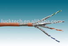
Like a cat6 network cable ?Personally, I'd patent an IC as a pair, where there is one overall cylindrical shield which serves as current return for both channels, and within I'd have two coax cables, one for each channel, where the braid of the smaller cables was tied at 1 end for electrostatic isolation interchannel.
Another practice to avoid 60Hz ground loops while you still have rfi removed --
You can use a cable with double shields (braid/foil) which are insulated from each other; ground one shield at source and other shield at load. You can increase the C between the two with addded external cap between shields. The Z is high at 60Hz and low at RF. center would be twisted pair for audio.
If you use triax cable, you can have the audio on the two shields only and not use the center at all... this keeps the highest flux density in the middle where L is highest, out of the audio path. Then use individual parallel wires spiral wound at 90 degress to each other for the tube conductors (shields) to kill L there (Mogami). The outer (3rd) shield does the rfi shielding and gets grounded at one end (c at other end for rfi bypass, if cable C isnt high enough). Thx-RNM
Last edited:
Like a cat6 network cable ?
For cancellation of external fields, yes. The twist does wonders.
But I was speaking about an overall shield.
As DF96 mentioned, not being truly concentric means that currents will not fully cancel the field outside the shield, and at any one spot, external magnetic fields can act on the core wire slightly different than the shield. But twisted, they'll tend to integrate out.
Cat 6 is not star, nor napoleonic. More like Absolute..with 2 olives rather than 3.
jn
If you use triax cable, you can have the audio on the two shields only and not use the center at all... this keeps the highest flux density in the middle where L is highest, out of the audio path.
Using both shields constrains the magnetic field of the audio signal to the space between the shields. There will be no magnetic field inside the inner shield, nor outside the outer one.
You've eliminated the 15 nH per foot component of internal inductance of the core wire by using a shield as core. By doing so, it will now have an internal inductance of 15nH times shield thickness/shield circumference. If the shield has 100 individual wires at 100% coverage, that would mean approximately 150 pH per foot inductance for the inner shield.
Then use individual parallel wires spiral wound at 90 degress to each other for the tube conductors (shields) to kill L there (Mogami). The outer (3rd) shield does the rfi shielding and gets grounded at one end (c at other end for rfi bypass, if cable C isnt high enough). Thx-RNM
I've no idea what you just said. Mogami says that? Link?
jn
I describe how to make shield/conductor which will over-come what you just said would happen with typically made shields. Nil L from shields. Mogami (Japan) did it this way, also. [reread the part about 90 degrees to each other. Signal on each wire of opposite polarity traveling at 90 degrees to each other.] But with triax configuration that I suggest using is a variation for 60hz ground breaking/sheilding. can apply to quad config as well. Thx-RNMarshUsing both shields constrains the magnetic field of the audio signal to the space between the shields. There will be no magnetic field inside the inner shield, nor outside the outer one.
You've eliminated the 15 nH per foot component of internal inductance of the core wire by using a shield as core. By doing so, it will now have an internal inductance of 15nH times shield thickness/shield circumference. If the shield has 100 individual wires at 100% coverage, that would mean approximately 150 pH per foot inductance for the inner shield.
I've no idea what you just said. Mogami says that? Link?
jn
Last edited:
My ex-wife was always efficient, even when she divorced me. Her major saying was, "Let's face the problems the next day when they come, one by one". And I have to admit, it was a good strategy, to deal with the major problems. However, it is the very long and inefficient way to optimize the system as the whole, optimizing sub-systems, but it is the one good algorithm to go, especially in our modern computer era of 0/1 digital reality.
Cambridge dictionary: esoteric - very unusual; understood or liked by only a small number of people, especially those with special knowledge.Fas42, on my point of view, math is NOT esoteric. "Sound of cables" is.
So far the discussion of "understood" or "accepted in the context of audio" cable behaviours over the last day or so has fitted under that umbrella, I believe. Haven't had time to digest the content of that period, but every bone in my body says the the "weirdo" stuff, like triboelectric and microphonic, gets on board, is attending the party, also. And that will be harder to understand, and explain.
Put it this way. Numerous times the SQ of my system has dropped, and I scatch my head, trying to work out what's gone wrong. Finally, I find something that fits into the weirdo category of causes, and voila, sound is fixed. You only have to do that, say, a few dozen times before slowly but surely the penny starts to drop ...
")
Frank
From what you wrote, I can't see how inductance is cancelled. Do you have a link that better describes the theory? Thanks.It describes how to make shield/conductor which will over-come what you just said would happen with typically made shields. Nil L from shields. Mogami (Japan) did it this way, also. But not with triax configuration that I suggest using. Only twin-axial config. Thx-RNMarsh
edit: I've re-read your words multiple times, I've still no idea.
As an aside, for a coax, there is no contribution of inductance for the outer shield anyway. The inductance of the coax is a direct function of the spacing between inner conductor and outer shield. Two wires at 90 degrees cannot cancel magnetic fields, the fields will add as a vector. That is why I am confused.
Um, are you on the right thread?My ex-wife was always efficient, even when she divorced me. Her major saying was, "Let's face the problems the next day when they come, one by one". And I have to admit, it was a good strategy, to deal with the major problems. However, it is the very long and inefficient way to optimize the system as the whole, optimizing sub-systems, but it is the one good algorithm to go, especially in our modern computer era of 0/1 digital reality.
jn
Last edited:
Cat 6 SSTPBut I was speaking about an overall shield.
Attachments
Last edited:
Forgive my poor English, in French, the same word carry a notion of 'occultism', magic.Cambridge dictionary: esoteric - very unusual; understood or liked by only a small number of people, especially those with special knowledge.
I don't understand why people, here, don't speak French like everybody.
- Status
- Not open for further replies.
- Home
- Member Areas
- The Lounge
- John Curl's Blowtorch preamplifier part II