Trivial explanations like 'oscillation' or change in capacitance are pointless. We know how to check for these things, we also know how to protect an audio product from being sensitive to small changes like capacitance. It is called 'engineering'. '-)
Well then apply some of that engineering John. Maybe a first step in ths direction would be for you to include an isolating inductor and Zobel network on your amplifier output.
We have Zobel networks already. Perhaps you should understand that it is in INTERCONNECT and INTERNAL HOOKUP WIRE that I am most interested in differences. I haven't changed my loudspeaker cable for the last 15 years.
Well then perhaps you should speak to somebody who devised a wide bandwidth test of amplifier susceptibility to IC ground loop currents? One which is capable of in situ sensitivity testing as opposed to benchtop tests which do not generally provide identical ground loops.
You know...something like this..
ps. With amp and pre on of course, monitor output of the amp.
Granted, it does not really work the amp supply wires, line cord wires, but hey, ya gotta do it one step at a time, right?
jn
Attachments
If you choose to continue, I recommend you learn enough t-line theory to understand the analysis. I unfortunately lost the testbook I used back in '74 or '75, perhaps somebody else can chip in with a reasonable text...certainly not Jackson or Becker...
Read above.
jn
My text circa 1969, Electromagnetic Energy Transmission and Radiation
Adler, Chu, and Fano
I knew Prof Adler but took this from Herman Haus.
jn, Bob I'm somewhat disappointed in your exchange, I would still like to observe these effects first hand but it is difficult. As for audibility I'm afraid my ears are not up to it.
Last edited:
Well then perhaps you should speak to somebody who devised a wide bandwidth test of amplifier susceptibility to IC ground loop currents?
My efforts is always to get as little HF contamination at the power amplifier output as possible. Measured in a whole audio chain. Wideband measurement and reduction of HF contamination by circuit design, shielding, grounding, wiring, PSU design, everything that matters. Reduction and minimization of HF contamination goes hand in hand with resulting "sound quality".
Thanks for providing the link. As you say, it illustrates what I have been saying. On the left side there is the equation for propagation constant, which may answer Esperado's question.jneutron said:http://www.belden.com/docs/upload/Pr...les-Part-1.pdf
If you look at page 1, they show a graph on the right hand side.
Be careful. At lower frequencies the line may have greater attenuation because a greater proportion of the series impedance is made of resistance. As I have said, your method and my method, if applied fully and correctly, must provide the same result as your impulses synthesise my audio waveform. Any deviation will be due to different approximations being used. The net result will be a small time delay and a small audio phase shift.If we adopt DF96's numbers, the mismatch is no longer 75 to 4, but 250 to 4. That requires even more reflections.
No. I am saying that if a system's sound changes as a result of an IC swap, before one begins to invoke pseudophysical explanations or even misappropriated physics explanations, one must first look at the obvious.JN are you telling me that the difference between quality and average wire is the tendency toward ground loops? '-)
You yourself had this issue when you were testing IC's on your equipment. Through careful repeated testings and trials, you found that cleaning your rca's thoroughly had an effect on your results. That is a classic groundloop behaviour. You also mentioned horiz scan intrusion as well, another classic ground loop problem.
Others have reported moving IC's back "into position" to modify a system sound. Another classic ground loop problem.
Power cord, same thing. That's why I include the power cords and duplex outlet in my test.
The materials choice for an IC will indeed alter the loop currents and how the signal return currents travel.
Amplifiers and sources which are susceptible to either creating ground loop currents, or responding to them are the primary smoking guns when it comes to ground loop issues. My test is to identify the sensitivities.
I include the source/preamp as well because it is part of the loop and can be sensitive that way. Whitlock, to the best of my knowledge, ignores outputs in his pin 1 tests. That is an error.
Sure. Or, on forum. Perhaps this thread since JC is interested?jn - I like this idea for a test very much. May I PM you to get more details? Its similar to the kind of things I've been banging on about on various boards for a couple of years on and off but don't gain much traction.
I am extremely disappointed. Both in how he brushed it all aside, and how I handled it..jn, Bob I'm somewhat disappointed in your exchange,
jn
Thanks for providing the link. As you say, it illustrates what I have been saying. On the left side there is the equation for propagation constant, which may answer Esperado's question.
Be careful. At lower frequencies the line may have greater attenuation because a greater proportion of the series impedance is made of resistance. As I have said, your method and my method, if applied fully and correctly, must provide the same result as your impulses synthesise my audio waveform. Any deviation will be due to different approximations being used. The net result will be a small time delay and a small audio phase shift.
Chapter 5 of my reference contains the derivation in the Belden white paper.
Listening tests performed are the evidence to me. I do not care we do not have an appropriate measuring method yet.
…
Indeed, this is also my approach.
Be careful. At lower frequencies the line may have greater attenuation because a greater proportion of the series impedance is made of resistance.
Absolutely concur. A #12awg will have net 2 milliohms per foot, so for a ten foot run, 100 transits is still only 2 ohms.
As the signal attenuates, the steps to final value become smaller, so more steps will be required. That's why I said before that it will cause a longer tail.
In the end of course, the final value across the simple 10 foot length will follow ohms law, but it takes time to get there. More time than my simplistic LC analysis would indicate.
jn
My efforts is always to get as little HF contamination at the power amplifier output as possible. Measured in a whole audio chain. Wideband measurement and reduction of HF contamination by circuit design, shielding, grounding, wiring, PSU design, everything that matters. Reduction and minimization of HF contamination goes hand in hand with resulting "sound quality".
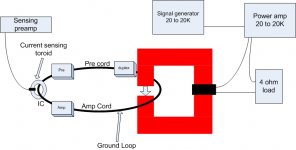
If you notice, my test is just a basic 20 to 20k stimulus of ground current. I had a spare dynaco 400 gathering dust in the basement, so decided to put it to use. I used a 4 ohm series resistor because I didn't like to have a pure inductance loading the amp. That tends to increase output stage dissipation as it goes hard 4 quadrant.
I used an open gap magnet to stimulate the ground loop for several reasons.
1. If I inserted a source into the ground loop, I alter the loop resistance. The purpose of the test is to do it in situ.
2. Using the gapped magnet allows me to just move the flux generator into the loop without disconnecting either PC's or IC's. The alternative, a toroid for example, would work just as well but requires disconnect. There have been anecdotal accounts of insertion contact problems, so I needed to remove that particular confounder.
3. I had one available...
")
I use a current viewing toroid for the same reasons as the loop magnetic drive. A non insertion capability of reading the drive current. Smaller is better of course, as it will slightly change the loop inductance as will the drive magnetics, but hey, something's gotta give.
The reason for the current view is to establish constant drive current. My intent is to establish a test protocol using standards, say 100 milliamps sine 20 to 20k, with a look towards either input referred or output referred coupling..swept.
It would be very good to do this while driving the poweramp hard as well, as there is also coupling between input supply currents from the line, supply dc line coupling to ground, and even mundane things like where the star connection for the input pair is and how it couples.
So watching the output spectra during a sweep no signal, or looking for a specific driven frequency buried within music.
The net end result? Step 1 in eliminating ground loop sensitivities of the equipment.
ah, where's my manners...
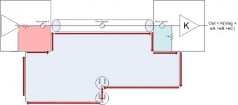
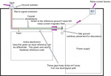
The pic on the left shows the couplings. Pink is the physical loop in the source component which will generate a voltage as a result of the ground current Blue is the same in the amp. edit(well, the origonal jpegs were pink and blue..) The IC error signal is the voltage generated by the rate of change of flux within the overall loop minus the flux created by the ground current which results.
The pic on the right is one method of taking the ground loop current and bypassing it's effects. It is based on the principle that a cylindrical shell of current has no internal field (the center black region of my avatar is the field map of a dual coax cable.) So I take the input ground reference wire, and pass it through that no field region within the current carrying conductor down to the reference node.
jn
Attachments
Last edited:
How do-you define "average" and "quality ?JN are you telling me that the difference between quality and average wire is the tendency toward ground loops? '-)
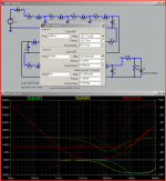
this is intended to address the claim that speaker impedance variation between channels - due to the speakers parameters varying with different operating point could cause "large" us delay "modulation" - due in part to cable Z
used 12' (repeated sections) of Pass 18 awg zip cord model from http://www.passdiy.com/pdf/spkrcabl.pdf
amp modeled with 1 uH isolation L
speaker 4 Ohm nominal @1, step definitions swap in C reactance to give ~ |4 Ohm| 1 kHz Z with ~75 degree phase angle @2
sorry about cursor window over schematic - but you should get the idea - the differential group delay between the loads is ~ 3.7us @1 kHz
to test cable Z role you could parameterize the cable Z - not thinking of that ahead of time - I instead raised the amp, speaker model Z 4x - with the result that the 1 kHz group delay difference dropped to ~900 ns
this basically should give the same result as dropping cable Z 4x with the same amp, speaker models
so it does look like single digit uS delays at audio are possible with zip cord, low Z speaker - and lower cable Z would reduce the effect
need to parameterize the cable - but a quick check shows that for the same L,C but 4 mOhm per section the group delay difference reduced to 1.2us @ 1 kHz so this low at least the effect seems to be dominated by cable series R
Attachments
Last edited:
Very nice indeed. The assuption that it scales is a good one.this is intended to address the claim that speaker impedance variation between channels - due to the speakers parameters varying with different operating point could cause "large" us delay "modulation" - due in part to cable Z
used 12' (repeated sections) of Pass 18 awg zip cord model from http://www.passdiy.com/pdf/spkrcabl.pdf
amp modeled with 1 uH isolation L
speaker 4 Ohm nominal @1, step definitions swap in C reactance to give ~ |4 Ohm| 1 kHz Z with ~75 degree phase angle @2
sorry about cursor window over schematic - but you should get the idea - the differential group delay between the loads is ~ 3.7us @1 kHz
to test cable Z role you could parameterize the cable Z - not thinking of that ahead of time - I instead raised the amp, speaker model Z 4x - with the result that the 1 kHz group delay difference dropped to ~900 ns
this basically should give the same result as dropping cable Z 4x with the same amp, speaker models
so it does look like single digit uS delays at audio are possible with zip cord, low Z speaker - and lower cable Z would reduce the effect
need to parameterize the cable - but a quick check shows that for the same L,C but 4 mOhm per section the group delay difference reduced to 1.2us @ 1 kHz so this low at least the effect seems to be dominated by cable series R
If you match cable to load, will the group delay drop to 0? If so, the model doesn't include the physical length. I'm not aware of how to include the actual physical length into the model.
What would be a good range of speaker impedances to verify? Is 1 to 60 reasonable?
jn
Is your amplifier a stereo input with unbalanced rca's?John N., thanks for the description of your test. In my case, I have everything in class II (so there is no galavanic ground loop, though loop is still closed through stray and parasitic capacitances).
If so, do you have it setup so that the shield return currents do not share?
jn
- Status
- Not open for further replies.
- Home
- Member Areas
- The Lounge
- John Curl's Blowtorch preamplifier part II