No, the schematic has been stable from the beginning, and enough PCB versions have been proposed to satisfy all tastes.Sir Elvee/Daniel, do we have a new/revised schematic of the standard Circlophone?.
Hi danielwritesbac,You're in for a wonderful treat of clear dynamic audio. A Circlophone is great fun.
Kindly advise what pcb layout should be used. Thanks in advance.
Regards,
Boyet
The majority of the listening tests were done with Wakibaki's RF resistant layout (there is one minor trace error--read the notes). Terranigma also has a similar layout listed and with less jumpers. These will assure the previously documented audible results. However, post 1 also contains other layouts and they all work well. Alex's is most convenient to build and to heatsink. There's really no way to answer your question since I didn't build all of them for comparison. I didn't use a PCB--mine is built on phenolic perfboard. I do like Terrangima's work and would personally choose to modify his CFP board to support the standard Circlophone schematic.
P.S.
See post 1 and pick whatever looks most attractive to you.
P.S.
See post 1 and pick whatever looks most attractive to you.
Last edited:
Hooray!!!
Maybe there will be room to do the offset trimmer more streamlined/clearly?
Transistors: The simulator reports that BC560C for input, 2SC5171 for vas, 2N5551 for q12/q13, 2N5401 for Q2/Q7, BC556B for Q1, MJ21194 for output, are ideal choices in theory; however, accuracy depends on the modeling files used.
One of these affects board layout.
Therefore, if it isn't too inconvenient, maybe you can add support for 2SC5171 vas (q5, q6) to decrease the amount of pin bend necessary to fit it?
Elvee tested Toshiba 2SC5171 and approved it as the answer for those seeking to build a more powerful Circlophone, since it will tolerate higher rail voltage, sounds great, and is much easier to heatsink.
Last edited:
Yes, Daniel, according to nature of Circlophone, I think that there isn't any negative issue about altering layouts regarding different pinouts. And more space for trimmer, that was on my mind too. My very first build was a modified Wakibaki layout according to use 2sa/2sc's at input without bending their legs. I have to re-gain my skills of Inkscape usage prior that operation.
You're in for a wonderful treat of clear dynamic audio. A Circlophone is great fun.
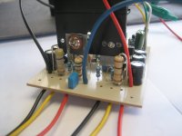
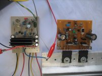
Here we go...
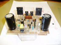
 the last pic was a size comparison with my compact P3A build..
 PCB was powerflux version.
Attachments
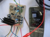
One thing super silent, at the time I was testing the amp I had to stick my ears on the speaker from time to time, making sure that I did not miss to attach the speaker wires. DC-offset at 06.0mv.
The music was Jazz of course, I am not that particular with vocals guess it comes to individual taste, some likes the powerful vocal range of a diva and to some the vocal distortion of a death metal band. Over all the distinctive melodic highlights & pleasant harmonies are ever present. Very good treble and bass response.

at the time I was testing the amp I had to stick my ears on the speaker from time to time, making sure that I did not miss to attach the speaker wires. DC-offset at 06.0mv.The music was Jazz of course, I am not that particular with vocals guess it comes to individual taste, some likes the powerful vocal range of a diva and to some the vocal distortion of a death metal band. Over all the distinctive melodic highlights & pleasant harmonies are ever present. Very good treble and bass response.
Thanks. Anyway, It was a test I was only using a linear -/+24vdc at around 2amps driving a 6ohm 50w JVC speaker, and by simply following the power chart table.
R21=33k
D8=10v 1w zener
D9=12v 1w zener
for the rest...
D4,D5 = 1N5822
Outputs=D1047
Phase splitter=BC546
Diff trannies=BC556B
*I have tested FR207 for D7, works OK too but I guess it has to be verified with SIM.
R21=33k
D8=10v 1w zener
D9=12v 1w zener
for the rest...
D4,D5 = 1N5822
Outputs=D1047
Phase splitter=BC546
Diff trannies=BC556B
*I have tested FR207 for D7, works OK too but I guess it has to be verified with SIM.
I'm so curious, with the phone/digiplayer source in your photo, how high did you need to set the gain? I'm thinking maybe 15k or 18k feedback resistor?
Got some notes. . .
The 2SD1047 is rated about that much too--Right about 3.5 amperes, the HFE takes a dive down to really low levels, causing the drivers to work extra hard. Driver kick sounds like, suddenly louder but with less treble. If you get that, try using the soft clip accessory (in post 1) and adjust it to suit your operating voltage. And if you happen to get a sort of scratchy treble, then try the thump stopper accessory (which is capacitive) or a little cap (range 470p to 1n5) instead of the thump stopper. Midrange is louder when C8, C9 are smaller, versus midrange quieter when C8, C9 are larger, so you can adjust that however you like. The 2A rated transformer needs at least 12,200u per rail power supply to help stiffen the rails (stiffer rails makes the lowest pitches louder). The H1/H2 (cold/warm) bass balance can be adjusted with NFB cap size, whereby larger is cold/thud bass very deep and smaller is warm bass with variety.
Analysis:
With your larger capacitance c8, c9 for laid back mids, and driver kick doing tame treble on dynamics, that probably sounds really great with jazz. The 2a transformer is performing safety current limiting, nicely protecting the 2sd1047 and the drivers (and the transformer's current limiting may be preventing driver kick noise). There's warm treble at high levels, natural treble at low levels, always laid back mids, and cold bass with some rumbles (would make a boomy speaker sound non-boomy or clearer). That's probably just perfect, but I'd try a 330u NFB cap as a warm bass experiment to see if you like a more old fashioned flair for jazz.
You've got a practically perfectly balanced set of parameters in your example. I'm impressed!
Wow, that's pretty close to the 50w speaker max.Thanks. Anyway, It was a test I was only using a linear -/+24vdc at around 2amps driving a 6ohm 50w JVC speaker, and by simply following the power chart table.
Got some notes. . .
The 2SD1047 is rated about that much too--Right about 3.5 amperes, the HFE takes a dive down to really low levels, causing the drivers to work extra hard. Driver kick sounds like, suddenly louder but with less treble. If you get that, try using the soft clip accessory (in post 1) and adjust it to suit your operating voltage. And if you happen to get a sort of scratchy treble, then try the thump stopper accessory (which is capacitive) or a little cap (range 470p to 1n5) instead of the thump stopper. Midrange is louder when C8, C9 are smaller, versus midrange quieter when C8, C9 are larger, so you can adjust that however you like. The 2A rated transformer needs at least 12,200u per rail power supply to help stiffen the rails (stiffer rails makes the lowest pitches louder). The H1/H2 (cold/warm) bass balance can be adjusted with NFB cap size, whereby larger is cold/thud bass very deep and smaller is warm bass with variety.
Analysis:
With your larger capacitance c8, c9 for laid back mids, and driver kick doing tame treble on dynamics, that probably sounds really great with jazz. The 2a transformer is performing safety current limiting, nicely protecting the 2sd1047 and the drivers (and the transformer's current limiting may be preventing driver kick noise). There's warm treble at high levels, natural treble at low levels, always laid back mids, and cold bass with some rumbles (would make a boomy speaker sound non-boomy or clearer). That's probably just perfect, but I'd try a 330u NFB cap as a warm bass experiment to see if you like a more old fashioned flair for jazz.
You've got a practically perfectly balanced set of parameters in your example. I'm impressed!
Sir Elvee,
Will it affect the amps performance if I increase C1(220n) to 330n, I'd like to use MKP film cap for C1 but what I got here was a 330n. I am now working on stereo a set-up. Powering it at +/-36vdc, everything gets hotter than usual maybe because I'm using 2SC5200/A1943 for the output, perhaps these faster devices do not fit on this amp.
TY!
Sir Daniel,
You have mentioned "thump stopper accesory", do you also mean at turn on & off?
Can you please show it to me in the schematic..
That cap is not critical: 220n is the optimum, but 330n will workSir Elvee,
Will it affect the amps performance if I increase C1(220n) to 330n, I'd like to use MKP film cap for C1 but what I got here was a 330n.
I don't think it is caused by the transistors, unless you have an oscillation.I am now working on stereo a set-up. Powering it at +/-36vdc, everything gets hotter than usual maybe because I'm using 2SC5200/A1943 for the output, perhaps these faster devices do not fit on this amp.
Remember that the quiescent current is higher than in most AB amplifiers: about 200mA, combined with your ~75V total supply, that's ~15W of quiescent dissipation which is quite noticeable, but there is nothing alarming there: everything is under control and servoed.
By itself, the Circlophone is natively dead silent at the turn-on/off. If you have that kind of problem, it could be caused by a preamplifier, or one of the supply polarity appearing earlier or later than the other.Sir Daniel,
You have mentioned "thump stopper accesory", do you also mean at turn on & off?
Can you please show it to me in the schematic..
Relief! that was reassuring Sir Elvee, I was actually tempted to DIY a temporary heatsink for TO-39 VAS in order to counter the heat dissipation of the transistors. There's this one "how posting" that shows solid copper wires being utilized as heatsink for the transistor and was actually soldered to the metal cap. I did the same using insulated copper wires in the shape of a coil and inserted it in the trannies metal top, but 00.4vac suddenly appeared at the output offset, well I guess it was a no-no for an amp, I figure the coil acted as antennae and picked up rf signal..
- Home
- Amplifiers
- Solid State
- Building Elvee's Circlophone: Documentation, Parts, Accessories, & beginner friendly