I think Elvee is preferring to leave listening impressions to the builders. And he already stated that he had tiny ears.
As a rule, I never assess subjectively something I have produced, be it something I cook, something I write, or an amplifier I build and design.
It's too easy to fool oneself.
The only sure way you can really make progress in any field is to use objective metrics, and rely on subjective impressions of others.
In this context:
I couldn't detect any difference.Did you, subjectively, like the little toshiba pair better or the big toshiba pair? Oh, I meant the audio quality?
The 2SC5171 has a marginally high collector capacitance (16pF), but it doesn't seem to hurt performances measurably or audibly.
I got my second board finished tonight and could finally try it with two speakers. I'm chuffed to bits! Sounds absolutely great, clear and detailed, very musical. Even my wife was impressed!
Here it is playing Simon and Garfunkels "Sounds of silence".
The heatsink will be uprated on the lefthand BD140's shortly
Here it is playing Simon and Garfunkels "Sounds of silence".
An externally hosted image should be here but it was not working when we last tested it.
The heatsink will be uprated on the lefthand BD140's shortly
Heatsink wizard
Congrats, and THANK YOU for showing that right side heatsink. That heatsink method (the comb looking "L-channel" piece) is preferable just like L-channel with holes drilled and T-Channel with holes drilled. That is the rarely seen "hot top heatsink" type referring to air movement having to go around+through a shelf, and they are remarkably good. Mine has insulator pads (for safety, for insulation and to block parasitic capacitance) on modified L-channel (very similar to the photo).
I'm also grateful to see the demonstration of output devices mounted on thick aluminum channel available at the hardware store. A vast array of re-cycling can be done that way, since whatever metal object is pasted and bolted to that thick channel will form a heatsink, like a row of square channel antenna tubing, a row of CPU heatsinks and really almost anything thermally conductive with significant surface area can form the heatsink fins.
I'm collecting data that gets used for documentation.
I'm curious, what all transistors did you use?
Like BD140?? ST, Harris, Philips, or something else?
P.S.
Photobucket (and similar) photos are prone to turning up missing, so I attached your photo to the forum so that it won't go missing in the future.
Soon there will be an outbreak of highly effective comb-fangle looking heatsinks all over diyaudio.com.I got my second board finished tonight and could finally try it with two speakers. I'm chuffed to bits! Sounds absolutely great, clear and detailed, very musical. Even my wife was impressed! Here it is playing Simon and Garfunkels "Sounds of silence". The heatsink will be uprated on the lefthand BD140's shortly
Congrats, and THANK YOU for showing that right side heatsink. That heatsink method (the comb looking "L-channel" piece) is preferable just like L-channel with holes drilled and T-Channel with holes drilled. That is the rarely seen "hot top heatsink" type referring to air movement having to go around+through a shelf, and they are remarkably good. Mine has insulator pads (for safety, for insulation and to block parasitic capacitance) on modified L-channel (very similar to the photo).I'm also grateful to see the demonstration of output devices mounted on thick aluminum channel available at the hardware store. A vast array of re-cycling can be done that way, since whatever metal object is pasted and bolted to that thick channel will form a heatsink, like a row of square channel antenna tubing, a row of CPU heatsinks and really almost anything thermally conductive with significant surface area can form the heatsink fins.
I'm collecting data that gets used for documentation.
I'm curious, what all transistors did you use?
Like BD140?? ST, Harris, Philips, or something else?
P.S.
Photobucket (and similar) photos are prone to turning up missing, so I attached your photo to the forum so that it won't go missing in the future.
Attachments
![tonedeafdiy_alex[1].jpg](/community/data/attachments/259/259322-36dc0a0a9c276482d821eb64c9ab6976.jpg)
Last edited:
Thanks for the kind words.
The BD140's are ST, MJ15003 are ON Semi and the 2N3019 are ST. The rest were in stock from 20+ years ago.
Hope that is of use.
Just to show how tolerant Elvee's design is. After listening for a while I became aware that the right channel seemed harsh in the upper registers. I checked all the connections etc and then the board. I finally noticed that R10 was not soldered at one end! Sounds even better now.
Last edited:
In this context:
I couldn't detect any difference.
The 2SC5171 has a marginally high collector capacitance (16pF), but it doesn't seem to hurt performances measurably or audibly.
I heard some people claiming that Japanese datasheet values specified within generous measurement margins. Maybe it is 8-12pF something else actually.
You're seeing driver versus vas balancing act--either both decent or one great.I heard some people claiming that Japanese datasheet values specified within generous measurement margins. Maybe it is 8-12pF something else actually.
The Toshiba 2sa1930/2sc5171 is the "both decent" example where both help each other slightly. Also seen with 2sa1358/2sc3421
The ST BD140/2n3019 is the "one great" example where the vas helps the driver. One of the prototypes used this combo and it measured well.
It is possible to alter this balancing act with layout as well, by reducing parasitic capacitance of the circuit boards.
Yes, thank you. I used the example to fine tune the "mouser parts example schematic" in post 1.Thanks for the kind words.
The BD140's are ST, MJ15003 are ON Semi and the 2N3019 are ST. The rest were in stock from 20+ years ago. Hope that is of use.
hi TonedeafDIY,
Did you omit the fuses on your Circlophone PCB?
Nice build, wonderfull sound, Great !
They were omited. This was because I could not find any fuse holders to fit Alex's pcb and based on no one else fusing at that part of the circuit! It will be fused though.
Thanks for the kind words, I'm just a rank amateur!
Hi Terranigma,
I'm not sure if I understand what you mean by dead silence "issues". My Circlophone is dead silent at full volume with my ear up against my speaker cones. I don't consider that an issue Other builds of other amps have had dead silence issues, usually just after grossly exceeding the output transistors SOAR
Ido not plan on mounting the drivers on the main heatsink so cannot comment on RF interference.
I'm not sure if I understand what you mean by dead silence "issues". My Circlophone is dead silent at full volume with my ear up against my speaker cones. I don't consider that an issue
Other builds of other amps have had dead silence issues, usually just after grossly exceeding the output transistors SOARIdo not plan on mounting the drivers on the main heatsink so cannot comment on RF interference.
Hi Terranigma,
I'm not sure if I understand what you mean by dead silence "issues". My Circlophone is dead silent at full volume with my ear up against my speaker cones. I don't consider that an issue
Ido not plan on mounting the drivers on the main heatsink so cannot comment on RF interference.
If you were familiar enough with main Circlophone thread, you may aware that I'm struggling with some RF Interference issue due to my location's heavy ambient RF noise. This very specific case for me. I recently noticed that if I connect driver heatsinks with a wire, RF issue remains in acceptable levels but not going to dead. I think my driver heatsinks working as antenna and I have to do something for proper grounding.
If you were familiar enough with main Circlophone thread, you may aware that I'm struggling with some RF Interference issue due to my location's heavy ambient RF noise. This very specific case for me. I recently noticed that if I connect driver heatsinks with a wire, RF issue remains in acceptable levels but not going to dead. I think my driver heatsinks working as antenna and I have to do something for proper grounding.
Chassis
Have you identified the bandwidth of the powerful radio signal? If so, then you could Avoid making any metal parts (heatsinks, cables) a multiple/division of that size signal. Try for "wrong size antenna" instead?
.
Power supply
Secondaries and diodes: Maybe the signal is coming over the power line, so try putting lossy little polyester dip cap (looks like green or red bubble) parallel to each diode of your bridge rectifier. About 10nF should do, but this size is mostly related to transformer size (range is 1nF to 15nF). If using efficient caps like polypro or ceramic, you'd need to make RC's (zobels) per each diode. If dulled sound, then use next size smaller caps. On success, "snubbed rectifier" will remove 1v to 1.5v of noise that you didn't need anyway, and you can measure that ~1v less on the rails.
This applies to standard diodes and convenient 1-piece bridge rectifiers. For fast/shottky diodes, a working method is somewhat different, but you can certainly put RC's across the transformer secondaries to limit the transformer passband to lower pitches.
Primaries: Next, try putting an MOV and an RC (or high voltage rated polyester dip cap/specialty AC cap) parallel with the transformer primary (mains)--you can recycle those mains rated pieces from the input of a retired computer power supply. The hookup is same as the input protection of the PC power supply. The point is to limit the passband at the transformer primaries down to allow lower pitches but hinder higher pitches.
Now both ends your power supply are somewhat RF resistant.
.
Amp Input
After that, you can also locate an RF filter at either side of your input cap (big uF cap pin must touch small pF cap pin if forming a blocker). A blocker looks like a voltage divider structure except that you've used caps instead of resistors for it. This blocker is also known as a CapDiv because of its appearance. The location for the added input filter is the spot where I put the thump blocker since it is also slightly capacitive. You can put a picofareds cap at that spot.
Heavy shield XLR cable is also workable for radio production (rf pollution) environment.
And then lastly, look at the schematic. See that 1M? It is a "token" load. This is power amp schematic, not integrated amp schematic. You'd probably want to shunt more than 1M worth of current if radio environment use. Instead of 1M, I'd probably start with 100k and then explore from there.
That spot is another good place for an RF filter. Those work better if RC instead of just a cap, so just make "tone control" that is higher than the audio band. Probably good is an RC//R--A super high pitched tone control parallel with a stronger input load. In this case there is dramatically increased load for all pitches higher than the audio band. This section is easy--play some classical and do it by ear. Just choose a cap small enough that it doesn't reduce your treble at all.
A last resort is a picofareds cap set from in+ to in- (same place as those 470R) to short out RF frequencies. Unfortunately that sort of filter also reduces the speed of the amp. It is probably okay to do that if you're not also maxing out your gain setting. Reducing the resolution also reduces the capacity for gain. This filter can work for high frequency radio like Megahertz FM radio as you are free to trim off anything faster than the amp. The prospect is abrupt and noticeable, so the cap size is easily found--just choose a small enough value that doesn't interfere with the main task of audio replay.
I hope these help.
Last edited:
Thank you Daniel, for your very kind support. If you taste quieteness of Circlophone first, there is no way to satisfy yourself with solutions those helping for "atteneuate" the problem. If you had destroy completely something evil once, you can't even bear the idea of living with a small portion of it again. I perceive that the problem is lying somewhere simple, somewhere front of my eyes..
If you take a look at photo of my very first Circlophone, you can see that driver transistors (2SA1930) have attached to the main heatsink using a piece of FR4 pcb board. After my last experiment with driver heatsinks, I felt that I'm on right direction. I want to play with them just before your helpful suggestions.
Thanks.
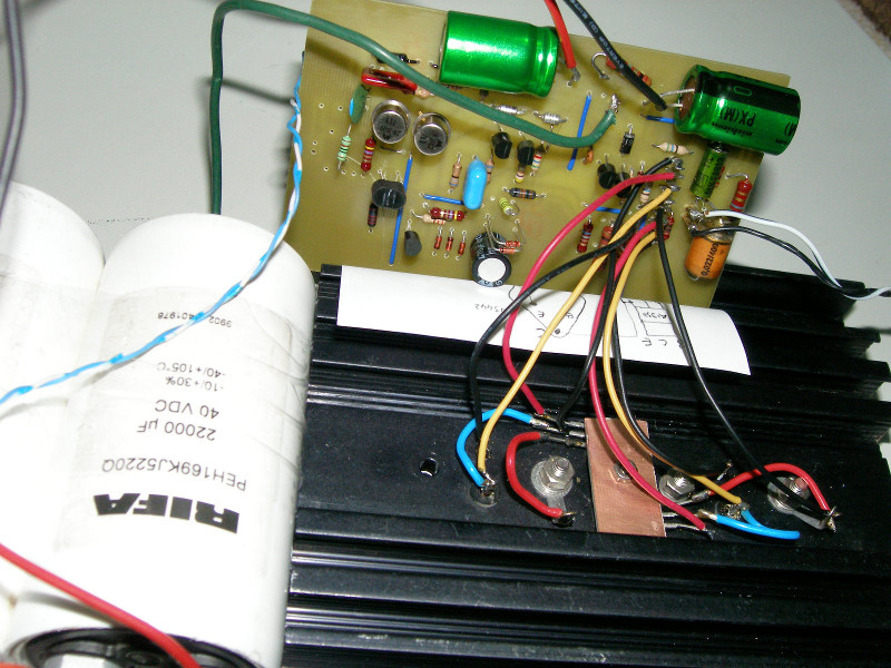
Last edited:
Something about that is unable to amplify RF.If you take a look at photo of my very first Circlophone. . .
Putting the drivers back onto the main heatsink, seems like a worthy experiment. Adding shields over the drivers and outputs shouldn't be a problem, but I'd go for a more secure mounting, like screws for the drivers this time, and good thermal pads to add electrical insulation for the Harris.
I keyed an FM transmitter (with the filters shut off for a raunchy output) right at a Circlophone, to no effect whatsoever, and then I keyed a 9 meter AM ("breaker breaker for a radio check?") and got absolutely nothin' out of the Circlophone, but there was a confounded truck driver about 6 miles away. Probably every T-amp in range (such as the neighbors--sorry guys) went bonkers but Circlophone stayed silent.
Last edited:
Maintenance post:
This post has replacement graphics displayed at post 1. Previously some graphics were at an off-site server; however, attaching graphics to a post makes a more durable presentation.
This post has replacement graphics displayed at post 1. Previously some graphics were at an off-site server; however, attaching graphics to a post makes a more durable presentation.
Attachments
I'm documenting C11, just in case someone wants to use output devices faster than the preferred devices listed in post 1. Extra speed is unnecessary for outputs; however, a reason to do it is if you happen to have some conveniently sitting around.
Just now I was told the common name for Q12, Q13 is "Negative Current Sensor" and that bit of documentation has been added at post 1, since it might assist discussion. This area of the Circlophone is sensitive, so one wants to use good quality authentic devices there.
Some people had trouble viewing the post 1 schematic on a tablet or netbook screen, so I put the schematic size at 1024x600 so one can use full screen display on a netbook and it will display clearly.
Here's the replacement with these three minor touch-ups.
Attachments
Sonic Signature
The transistor with the most effect on sonic signature is the outputs.
Elvee provided a list with a quality score for outputs and then I edited the listing at post 1 to only good varieties.
The transistor with the most effect on sonic signature is the outputs.
Elvee provided a list with a quality score for outputs and then I edited the listing at post 1 to only good varieties.
- Home
- Amplifiers
- Solid State
- Building Elvee's Circlophone: Documentation, Parts, Accessories, & beginner friendly