on the pit lane with very fast (HEX/MOS)FET CFA designed for high PSRR at high frequencies...Very fast bipolar CFA designed for high PSRR at high frequencies may sound great, I agree. Tough competition to JFET miracles
Ultra compact and nice resuming, PMA.
My dilemma with servos are what caps to use in them? Are they contributing as much colouration as a series DC blocking cap? I often use 220n - 2u2 PP caps for my servos but to make these caps a "super" cap, cost a small fortune and takes up huse amounts of PCB space....
/S
/S
If you want the 'hand carved by virgins' sound, I should think that you must go to the Mundorf or similar cap. In fact, in a project that I am associated with, the first cap, a typical mylar, was changed to Rel, with great subjective improvement, then 'Mundorf with even a further subjective improvement. I recommended a SERVO to remove the cap completely.
If you use a Fet Op. Amp, the inverting input impedance is so high that you really don"t care about any inductance or resistance of the cap.My dilemma with servos are what caps to use in them? Are they contributing as much colouration as a series DC blocking cap? I often use 220n - 2u2 PP caps for my servos but to make these caps a "super" cap, cost a small fortune and takes up huse amounts of PCB space....
The cap can have only an influence at frequencies lower than the cutting frequency of the low pass filter.
Means far away from the audio range, as you can set this frequency very low.
Because the high impedance, you can use any polypro film cap, and concentrate on the quality of the op amp: Low noise, low drift and offset; unity gain stable.
Not to mention that, with a good design, paired and thermally coupled parts, you can design an amp with a drift and offset low enough that you can forget about-it.
And a clever protection circuit can protect-it against DC in the input, as well he can protect your speaker from amp failure.
I do not have any serial cap in all my home system.
And a clever protection circuit can protect-it against DC in the input, as well he can protect your speaker from amp failure.
I do not have any serial cap in all my home system.
Are you going to share your circuit 'secrets' with us, Esperado? '-)
On my part, I usually use a quality mylar cap for the servo, BUT I do make sure that the servo is operating well below the audio bandwidth. Servos become subjectively problematic if care is not taken to decouple them and to keep the bandwidth very low. Still, I am often reminded that better caps make better servos. It is most likely true.
On my part, I usually use a quality mylar cap for the servo, BUT I do make sure that the servo is operating well below the audio bandwidth. Servos become subjectively problematic if care is not taken to decouple them and to keep the bandwidth very low. Still, I am often reminded that better caps make better servos. It is most likely true.
Are you going to share your circuit 'secrets' with us, Esperado? '-)
On my part, I usually use a quality mylar cap for the servo, BUT I do make sure that the servo is operating well below the audio bandwidth. Servos become subjectively problematic if care is not taken to decouple them and to keep the bandwidth very low. Still, I am often reminded that better caps make better servos. It is most likely true.
Hi John,
See Section 8.4 on page 167 in my book for a description of using the DC servo integrator output for detecting DC offset for protection. See also page 335 under Loudspeaker Protection Circuits.
Cheers,
Bob
Yes, John.Are you going to share your circuit 'secrets' with us, Esperado? '-).
By example, my protection circuit. (I will soon open a thread in this diyAudio forum)
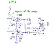
http://www.esperado.fr/images/stories/protection-totale-definitive.gif
It is based on a very simple idea: "What is a healthy working amp ? " -> A device who provide an output signal similar to the input one (level apart).
If you compare with a comparator or Op amp the input signal with the output signal divided by the gain factor of the amp, any noticeable difference will indicate a failure. Whatever DC, oscillation, or output short circuit, it will work instant.
You can do the same to compare a direct input signal with the same signal across a cap (low FC enough). if any difference (DC in the input) the protection will fire instant.
The circuit can look complicated, it is not. Just added soft start and power supply for the protection. Can be plugged in any existing amp.
The first OP amp is a comparator for two channels. followed by a rectifier stage, and an amplifier for the error signal. Just an added cap in the input signal do the job to protect your direct coupled amp form any DC at the input.
I use this kind of comparator to evaluate how behave any amp in real condition (musical signal and real loudspeaker charge), looking at the difference signal. Always affraying !!!
Because those terrific distortions (far from static measurements) and the phase errors, you have to carefully tune the level where the error signal fire your protection.
Last edited:
U1 compare the left channel input and output, U2 the right channel. The 2X5 k adjustable are tuned to divide the output signal to the level of the input one, depending on the Amp gain factor.
The ouput signals are mix together and rectified by the U3 stage. The 1Mo trim is used to tune the gain of the error signal. Followed by a diode to set an hysteresis and have a clear firing point..
I had this idea around 1975. Simple, isn't-it ? And do not suffer any delay introduced by the integrators usually used to detect DC in the output.
Attachments
Last edited:
Hi John,
See Section 8.4 on page 167 in my book for a description of using the DC servo integrator output for detecting DC offset for protection. See also page 335 under Loudspeaker Protection Circuits.
I did something similar, detecting the moment when integrator saturates. But I used integrator's input, instead of output. From this moment it's time constant decreases many times, and catching up this moment I switch protection relays: when servo can't catch up that definitely means that something is very wrong and speakers have to be disconnected.
Thanks, John, a compliment from you is something precious for me.Great idea, Esperado.
As promise, i have opened a thread here:
http://www.diyaudio.com/forums/solid-state/221737-ultimate-amp-protection-circuit.html
Will see if any cooperation with other DIYers here can lead to a final ready to use project, with PCB etc...
What are your thoughts on using an NTC thermistor in an appropriate spot?Has anyone tried thermal feedback?
Frank
What are your thoughts on using an NTC thermistor in an appropriate spot?
Frank
There are uses for that, I was thinking of applying a heat gradient to the input pair as a servo. A tiny Peltier goes both ways and the thermal time constant subs for the integrator. A more subtle point is that since thermals are fractinal f in frequency response it might be unconditionally stable (no motorboating).
Hi, mr Marsh, I had answered this question here: http://www.diyaudio.com/forums/solid-state/221737-ultimate-amp-protection-circuit.html#post3205580Just wondering why not use the amps built in error correction port, amplify it, rectify it and drive relay with it for protection?
- Status
- Not open for further replies.
- Home
- Member Areas
- The Lounge
- John Curl's Blowtorch preamplifier part II