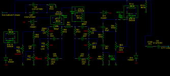
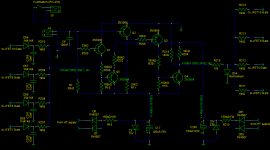
Ok, I added some resistors to the EQ section's JFETs, too. I hope I have understood this right. Here is the entire EQ section. The green rectangles show the JFET positions. I also added R115, upwards and to the right, as reference to ground.
Is it correct?
Is it correct?
Attachments
Yes, of course it does. So, if i understand correctly, I have to create a positive rail supply as well, just as in Kevin's suggestion, correct?Hope this makes sense
As for JFET 8 & 9, Should I just tie their Sources (output) to ground via a 1MΩ resistor?
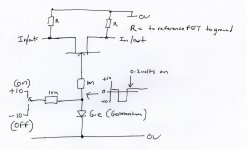
Yes, positive supply to turn them on fully but that supply must be clamped to stop the gate going more positive than around 0.2 volts. Thats what the germanium diode does. If you don't use a positive supply and just switch to ground then you lose (and its very FET dependent) quite a bit of the available "on" resistance. Whether that matters so much here is up to you you as all the circuitry is so high impedance anyway.
The FET sources do need tying to ground. 1MΩ or even higher.
But you MUST now try this for real. Don't just take my word for it all
The FET sources do need tying to ground. 1MΩ or even higher.
But you MUST now try this for real. Don't just take my word for it all
I see. So in your schematic the germanium diode pulls almost all this V+ to Ground, right? Wouldn't a reversed fast-turning diode in series to the gate do the same?Yes, positive supply to turn them on fully but that supply must be clamped to stop the gate going more positive than around 0.2 volts. Thats what the germanium diode does. If you don't use a positive supply and just switch to ground then you lose (and its very FET dependent) quite a bit of the available "on" resistance. Whether that matters so much here is up to you you as all the circuitry is so high impedance anyway.
I put 2M2Ω there.The FET sources do need tying to ground. 1MΩ or even higher.
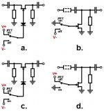
I know. I am posting the full switching system together with the supplies. On the left I have Kevin O'Connor's design, and on the right yours.But you MUST now try this for real. Don't just take my word for it all
I don't want it to look like some kind of debate or anything, it's just that I want to understand how this works and which is better. So here are my latest questions and I promise I won't tire you more!
1. If I wish to add an RC net, should a cap to GND be placed between the 1MΩ resistor and Gate ?
2. Where can I find a Germanium diode? I searched Mouser and Elfa, they do not have any...
Attachments
Yes, the germanium diode pulls or clamps the control line to 0.2v As you have drawn it, all the gates are driven together and so if that is how you will really use it then you can economise and use just one diode. Just tie all the 1Meg gate resistors together and feed them from the top of one diode.
No germanium diodes
Then modify the control circuit to produce the required 0.2 volts. Just thinking aloud on this... you can work the values out
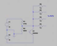
Feed the collector of Q4 from the junction of two series resistors. These resistors are connected between 15v and ground. Use say a 10K for the "top resistor and calculate the bottom one... OK I'll do it... its 130 ohms give or take.
Yes Will that work ? Try it
No germanium diodes
Then modify the control circuit to produce the required 0.2 volts. Just thinking aloud on this... you can work the values out
Feed the collector of Q4 from the junction of two series resistors. These resistors are connected between 15v and ground. Use say a 10K for the "top resistor and calculate the bottom one... OK I'll do it... its 130 ohms give or take.
Yes
Will that work ? Try it Aha, so the 10k-Diode junction becomes common, right?Yes, the germanium diode pulls or clamps the control line to 0.2v As you have drawn it, all the gates are driven together and so if that is how you will really use it then you can economise and use just one diode. Just tie all the 1Meg gate resistors together and feed them from the top of one diode.
I'll also use 1N4148 for the diodes, instead of the germanium ones! I hope it worksNo germanium diodes
Then modify the control circuit to produce the required 0.2 volts. Just thinking aloud on this... you can work the values out
Not sure if I understood that last part. U mean like that?Feed the collector of Q4 from the junction of two series resistors. These resistors are connected between 15v and ground. Use say a 10K for the "top resistor and calculate the bottom one... OK I'll do it... its 130 ohms give or take.
An externally hosted image should be here but it was not working when we last tested it.
*sigh* U know, The amp is already built on 2 eyelet boards, one facing upwards and one facing downwards. And the stupid thing is that the V- and V+ rails for the switching are located... Guess where!Yes
Heh, anyway it's fun and I am learning and these coming weekends will be amazing!
Thanks for the help, Mooly! When I come to England, or if you come by Sweden I am buying beers while jamming with the amp (if you drink, that is)!
10K and 130ohm in series across 15 volts generate around 200mv across the 130 ohm. That 0.2 volts can be used as a voltage rail to supply the collector of Q4. So then Q45 would switch between -15 and 0.2v.
IN4148 or any silicon diode won't work inplace of the germanium. The 0.6 volts generated is to high and would breakthrough the FET gate junction giving a DC offset on the audio.
IN4148 or any silicon diode won't work inplace of the germanium. The 0.6 volts generated is to high and would breakthrough the FET gate junction giving a DC offset on the audio.
I think my schem is wrong. The R204(100k) is not needed, since the 10k is there for providing V+.
I found American Semiconductors Inc., they also have an online store here:
store.americanmicrosemiconductor.com
I found American Semiconductors Inc., they also have an online store here:
store.americanmicrosemiconductor.com
Last edited:
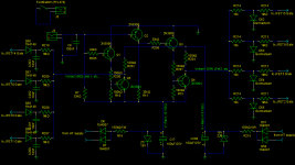
Oops! Sorries, I'll number them correctly when I get home!Pictures a bit small but there seem to be three ? R214's
I visited his website, has great info indeed! Thank you!A good example of a commercial j-fet input selector is the lecson ac1 pre-amp
the circuit can be found on Paul Kemble s web site
Thank you Merlin. It is, indeed. I am starting to understand how JFETs really work. This picture shows a N-channel JFET, right?Merlinb said:Thought this summary diagram of FET series and shunt switching might be useful in this thread
Fixed numbering and removed the excess resistor. Check it out!Mooly said:Pictures a bit small but there seem to be three ? R214's

Attachments
 Now you can remove the germanium diode (because the resistor network R218 and R204 generate the 0.2 volts reference when the transistor is off). Also the resistor R219 can be linked out.
These two resistors (R218/204) now need to be higher in value as I showed in the diagram earlier using 470K and 6K8. Do you see why ? It is because when Q4 is on the resistor R218 is connected via the transistor across the -15 volt supply. 140 ohm is wasteful of current and it would get hot. So I decided on 6K8 and 470K to keep the ratio similar.
But you MUST MUST MUST
build this as a test circuit to confirm it works.Ok, removed the germanium diode (I was about to order some, btw
) and removed also R219. Should I put some 10nF caps to ground after the 1MΩ resistors?I saw it now!These two resistors (R218/204) now need to be higher in value as I showed in the diagram earlier using 470K and 6K8. Do you see why ? It is because when Q4 is on the resistor R218 is connected via the transistor across the -15 volt supply. 140 ohm is wasteful of current and it would get hot. So I decided on 6K8 and 470K to keep the ratio similar.
Well, I use 1% 1/2W metal film resistors. If I did the calculation correct it's 0.0003W Power dissipation. But I changed them, as you said it is a waste.Ok, ok!But you MUST MUST MUST
This weekend I will do the order and possibly start to prepare the eyelet board. It may take a while, but I'll keep you updated!
Again, thanks to all of you and especially to you Mooly! And the beer/wine/orange juice/whatever is on!

If we had used 140 ohm it would have been drawing over 100ma and dissipating 1.6 watts
Adding caps after the 1M will add a time constant and could give the impression of "softer" switching. Maybe a bit lower like 0.01uf.
But all this is why I say you have to build at least one working switch element to prove all is OK. I know FET's work really well and I tested them exhaustively in my preamp design to get the best results but yours is a bit different overall.
So please don't just take it as a fully tested and worked design because it isn't.
Yikes! Then my math was wrong or I'm missing something....If we had used 140 ohm it would have been drawing over 100ma and dissipating 1.6 watts
But isn't 0.01uF = 10nF ?Mooly said:Adding caps after the 1M will add a time constant and could give the impression of "softer" switching. Maybe a bit lower like 0.01uf.
No, I am not taking it for granted, that's for sure. No worries on that!Mooly said:But all this is why I say you have to build at least one working switch element to prove all is OK. I know FET's work really well and I tested them exhaustively in my preamp design to get the best results but yours is a bit different overall.
So please don't just take it as a fully tested and worked design because it isn't.
Thanks again!
- Status
- This old topic is closed. If you want to reopen this topic, contact a moderator using the "Report Post" button.
- Home
- Live Sound
- Instruments and Amps
- JFETs as switch in 2-channel tube amp