Harrison, would you quantify their individual results so that it can be used as a measure here, I think the first oscilloscope traces from Routhun at http://www.diyaudio.com/forums/solid-state/198500-symef-amplifier-80.html explains a whole lot, if there are others that could provide the same a very definite conclusion can be drawn.
Besides that I have been lurking in the dark shadows on your thread to see what is brewing, out of pure interest for where it is going and I would not miss the all revealing formula for anything in the world.
I am not joking - there are those who can successfully market any product and this may be one golden method so I am not laughing at the back of your head. Not yet anyway.
Does anyone know what the Volt-Amp and Output Vrms ratings were, of the transormer used for that square wave test?
Tom @ #1172,
Tom, thats not actually correct - there is mutual inductance regardless of whether or not they share some length of conductor, as long as the flux of one current-carrying loop cuts another current-carrying loop (think loop antennas).
If the currents share some length of conductor then there is more mutual inductance - this forces the flux of one loop to cut the other - it has to, as they share a common conductor.
This shared-conductor method is actually quite common in small loop antennas, and is used for impedance transformation. The transmitter drives a small (often rectangular) loop, which shares a segment with the main transmitting loop, making what is basically an air-cored transformer (hence the impedance transformation)
I should have pointed this out some time ago, but forgot. sorry, my bad.
Unfortunately this kind of ruins your "n parallel sets of wiring" approach - in order for that method to work in practice, you must ensure that there is little or no magnetic coupling between the parallel sets of wiring.
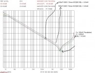
This also occurs when you parallel a pair of film capacitors - the overall ESL does go down, but it does not halve. see the attached plot. I paralleled a pair of 5.9nH 100nF Panasonic ECQE caps, and the resultant inductance was 4nH, not 3nH as you might expect. the caps were hard against each other (6mm between pins), and I calibrated out the test fixture PCB they were mounted on.
interestingly enough this doesnt really happen when you parallel electrolytics (on a PCB set up as a parallel-plate transmission line) as most of the ESL is inside an AL can, which does a pretty good job of eddy-current shielding (what with ESL effects occurring at high frequencies). If, however, you have a horrible wiring layout (ring terminals and widely spaced wires) rather than a well laid out DS-PCB, then all the wiring inductances mutually couple (IOW with electrolytics the overall ESL is dominated by the wiring/pcb layout)
Even with planes, the problem that can partially ruin the improvement from paralleling is when the conductors are no longer completely separate, i.e. the currents have to share some length of conductor. Then there would be MUTUAL inductance. And that wrecks the algebra somewhat so that the inductances don't fully reduce from paralleling.
Tom, thats not actually correct - there is mutual inductance regardless of whether or not they share some length of conductor, as long as the flux of one current-carrying loop cuts another current-carrying loop (think loop antennas).
If the currents share some length of conductor then there is more mutual inductance - this forces the flux of one loop to cut the other - it has to, as they share a common conductor.
This shared-conductor method is actually quite common in small loop antennas, and is used for impedance transformation. The transmitter drives a small (often rectangular) loop, which shares a segment with the main transmitting loop, making what is basically an air-cored transformer (hence the impedance transformation)
I should have pointed this out some time ago, but forgot. sorry, my bad.
Unfortunately this kind of ruins your "n parallel sets of wiring" approach - in order for that method to work in practice, you must ensure that there is little or no magnetic coupling between the parallel sets of wiring.
This also occurs when you parallel a pair of film capacitors - the overall ESL does go down, but it does not halve. see the attached plot. I paralleled a pair of 5.9nH 100nF Panasonic ECQE caps, and the resultant inductance was 4nH, not 3nH as you might expect. the caps were hard against each other (6mm between pins), and I calibrated out the test fixture PCB they were mounted on.
interestingly enough this doesnt really happen when you parallel electrolytics (on a PCB set up as a parallel-plate transmission line) as most of the ESL is inside an AL can, which does a pretty good job of eddy-current shielding (what with ESL effects occurring at high frequencies). If, however, you have a horrible wiring layout (ring terminals and widely spaced wires) rather than a well laid out DS-PCB, then all the wiring inductances mutually couple (IOW with electrolytics the overall ESL is dominated by the wiring/pcb layout)
Attachments
"Parallel decoupling capacitances", taken to one of its logical conclusions:
Gootee
With the common tie at both ends of the wire pairs your relying on mutual inductance to persuade the current paths, much like parallel planes would.
Would be interested in seeing the effectiveness of this approach for audio.
Too much math for a weekend, will follow up though.
Thanks
-Antonio
Folks,
in theory you can indeed play with the wiring and get things to cancel out. In practice however you cannot - believe me I've tried. unless you can accurately model the entire physical assembly (eg PCB parasitic extraction) you will have little or no idea exactly what mutual couplings you have where. Even better is to be able to accurately measure the overall impedances in-situ.
I spent about 3 months working on this a couple of years ago - it was a DM filter for a PFC flyback smps. the first 8-10 weeks were spent fiddling around with various stupid layouts, measuring the results with EMI scans, and not getting anywhere. then I spent a bit of money and bought an HP-35676 50R signal divider for my HP3577A network analyzer, bought/made some calibration standards and started to accurately measure the actual impedances on assembled PCBs.
Once I could accurately, repeatably measure down below 1nH (up to 200MHz) I made significant progress in 2 weeks. Until then, I got nowhere - even though I've got 15yrs experience in this area, guessing my actual parasitics just wasnt good enough.
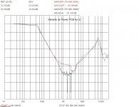
See the attached plots. The red trace on "EMI filter 1.jpg" was where I started, and I managed to get to the black trace after 8 weeks - all I managed to do was make a 20dB improvement between 600kHz and 2MHz, but all my efforts had no effect whatsoever above 2MHz.
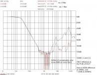
Once I could actually measure the in-situ impedances though, I got to the red trace on "EMI Filter 2.jpg" in 1 PCB revision. I took those plots using the same inductors and capacitors - I de-soldered them from the rev 1 PCB and soldered them onto the rev 3 PCB. t took 2 weeks, but 1 week was waiting for PCBs, and about 0.5 weeks learning how to make the precise measurements. it really only took 1 day to get an extra 60dB attenuation at 30MHz.
This is why I harp on about parallel-plate transmission lines for multiple paralleled caps. all you need to do is not chop great big holes in your V+(V-) & 0V planes and voila, you get an excellent, broadband layout. try pulling clever tricks without measuring anything and you just wont (think wheelstands and endos at 100mph with your eyes shut. how well is that likely to turn out)
in theory you can indeed play with the wiring and get things to cancel out. In practice however you cannot - believe me I've tried. unless you can accurately model the entire physical assembly (eg PCB parasitic extraction) you will have little or no idea exactly what mutual couplings you have where. Even better is to be able to accurately measure the overall impedances in-situ.
I spent about 3 months working on this a couple of years ago - it was a DM filter for a PFC flyback smps. the first 8-10 weeks were spent fiddling around with various stupid layouts, measuring the results with EMI scans, and not getting anywhere. then I spent a bit of money and bought an HP-35676 50R signal divider for my HP3577A network analyzer, bought/made some calibration standards and started to accurately measure the actual impedances on assembled PCBs.
Once I could accurately, repeatably measure down below 1nH (up to 200MHz) I made significant progress in 2 weeks. Until then, I got nowhere - even though I've got 15yrs experience in this area, guessing my actual parasitics just wasnt good enough.
See the attached plots. The red trace on "EMI filter 1.jpg" was where I started, and I managed to get to the black trace after 8 weeks - all I managed to do was make a 20dB improvement between 600kHz and 2MHz, but all my efforts had no effect whatsoever above 2MHz.
Once I could actually measure the in-situ impedances though, I got to the red trace on "EMI Filter 2.jpg" in 1 PCB revision. I took those plots using the same inductors and capacitors - I de-soldered them from the rev 1 PCB and soldered them onto the rev 3 PCB. t took 2 weeks, but 1 week was waiting for PCBs, and about 0.5 weeks learning how to make the precise measurements. it really only took 1 day to get an extra 60dB attenuation at 30MHz.
This is why I harp on about parallel-plate transmission lines for multiple paralleled caps. all you need to do is not chop great big holes in your V+(V-) & 0V planes and voila, you get an excellent, broadband layout. try pulling clever tricks without measuring anything and you just wont (think wheelstands and endos at 100mph with your eyes shut. how well is that likely to turn out)
Attachments
Gootee
With the common tie at both ends of the wire pairs your relying on mutual inductance to persuade the current paths, much like parallel planes would.
Would be interested in seeing the effectiveness of this approach for audio.
Too much math for a weekend, will follow up though.
Thanks
-Antonio
I simulated it. See links near beginning of this thread.
Originally Posted by gootee
Even with planes, the problem that can partially ruin the improvement from paralleling is when the conductors are no longer completely separate, i.e. the currents have to share some length of conductor. Then there would be MUTUAL inductance. And that wrecks the algebra somewhat so that the inductances don't fully reduce from paralleling.
Tom, thats not actually correct - there is mutual inductance regardless of whether or not they share some length of conductor, as long as the flux of one current-carrying loop cuts another current-carrying loop (think loop antennas).
If the currents share some length of conductor then there is more mutual inductance - this forces the flux of one loop to cut the other - it has to, as they share a common conductor.
This shared-conductor method is actually quite common in small loop antennas, and is used for impedance transformation. The transmitter drives a small (often rectangular) loop, which shares a segment with the main transmitting loop, making what is basically an air-cored transformer (hence the impedance transformation)
I should have pointed this out some time ago, but forgot. sorry, my bad.
Unfortunately this kind of ruins your "n parallel sets of wiring" approach - in order for that method to work in practice, you must ensure that there is little or no magnetic coupling between the parallel sets of wiring.
This also occurs when you parallel a pair of film capacitors - the overall ESL does go down, but it does not halve. see the attached plot. I paralleled a pair of 5.9nH 100nF Panasonic ECQE caps, and the resultant inductance was 4nH, not 3nH as you might expect. the caps were hard against each other (6mm between pins), and I calibrated out the test fixture PCB they were mounted on.
interestingly enough this doesnt really happen when you parallel electrolytics (on a PCB set up as a parallel-plate transmission line) as most of the ESL is inside an AL can, which does a pretty good job of eddy-current shielding (what with ESL effects occurring at high frequencies). If, however, you have a horrible wiring layout (ring terminals and widely spaced wires) rather than a well laid out DS-PCB, then all the wiring inductances mutually couple (IOW with electrolytics the overall ESL is dominated by the wiring/pcb layout)
Terry,
Thanks for the important corrections. Bummer.
What if the paralleled pairs were each tightly twisted (but not with any of the other pairs)? And what about using shielded twisted pair cables?
I guess the logical extension of the n pairs is a pcb like you showed. That seems like the way to go. I just thought it would be nice to also have a point-to-point-wiring method that could achieve something similar. Sounds like it can't work very well. Maybe we should try it, just to see what happens.
Tom
Last edited:
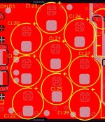
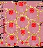
here is a parallel-plate transmission line pcb layout.
As you can see the PCB layout is very, very simple. the top layer is +Vdc (+24V in this case), the bottom layer is 0V. and each layer is almost entirely solid Cu, only having holes in it where unconnected component legs are.
this is much, much easier than trying to use parasitics as design elements - with or without fancy measuring gear or unbelievably expensive parasitic extraction software.
Attachments
When I do this, it is with very high loss polyester dip caps, and with much care with comparisons to see if there's any benefit to it. I'm quite likely to accept filters that give BOTH higher resolution audio AND cooler heatsink. Thus, although you'll catch me doing it, just know it wasn't done arbitrarily. Considering the ESR of the little dip caps in use, assume an RC exists.Argh!! Where does this idea of always throwing in a parallel film cap keep coming from? Please read the thread about paralleling electrolytics and film caps. It is NOT, repeat NOT, a good idea, especially way out at the PSU reservoir caps. It MIGHT, but only might, be safe-enough, and would even have a chance of being effective, right at the load, for decoupling. Similar "discouraging" comments are waiting for the next mention of placing a film cap (or any cap, by itself) across a rectifier diode.
Actually, I'm afraid that some people will find my designs and corrupt the filters by using high efficiency ceramic/polypro/box caps. This really happens when some people just feel the need to pay extra for more decorous looking capacitors. And it goes badly.
In fact the only caps that work appropriately in my filters are polyester dip (bubble, not box) cap and tiny value electrolytic. Sometimes, a very high voltage electrolytic can be used but that is on a case-by-case basis.
On my new TDA7294 point-to-point design, I wish I could translate the 3n3 vs 2u2 vs 3n3 capdiv power filter into RC's. I'm sorry that I forgot to mention that those are all hi-loss filter purpose polyester caps. The 2u2 from rail to rail is particularly hard to select for adequate ESR and would be much easier as an RC, instead.
Last edited:
When I do this, it is with very high loss polyester dip caps, and with much care with comparisons to see if there's any benefit to it. I'm quite likely to accept filters that give BOTH higher resolution audio AND cooler heatsink. Thus, although you'll catch me doing it, just know it wasn't done arbitrarily. Considering the ESR of the little dip caps in use, assume an RC exists.
Actually, I'm afraid that some people will find my designs and corrupt the filters by using high efficiency ceramic/polypro/box caps. This really happens when some people just feel the need to pay extra for more decorous looking capacitors. And it goes badly.
In fact the only caps that work appropriately in my filters are polyester dip (bubble, not box) cap and tiny value electrolytic. Sometimes, a very high voltage electrolytic can be used but that is on a case-by-case basis.
On my new TDA7294 design, I wish I could translate the 3n3 vs 2u2 vs 3n3 capdiv filter into RC's. I'm sorry that I forgot to mention that those are all hi-loss filter purpose polyester caps. The 2u2 from rail to rail is particularly hard to select for adequate ESR and would be much easier as an RC.
Well, if your heatsink gets cooler, at least it's probably not oscillating at high frequency.
I guess you could probably save the unsuspecting folks from messing up the designs with low-loss caps by just using low-loss caps with a small resistance in series.
here is a parallel-plate transmission line pcb layout.
As you can see the PCB layout is very, very simple. the top layer is +Vdc (+24V in this case), the bottom layer is 0V. and each layer is almost entirely solid Cu, only having holes in it where unconnected component legs are.
this is much, much easier than trying to use parasitics as design elements - with or without fancy measuring gear or unbelievably expensive parasitic extraction software.
So, if we had a board like that (or one for each power rail, I guess), which stretched from the rectifier bridge to the active devices and load ground point of an audio power amplifier, we wouldn't need much in the way of decoupling capacitors, right? I think you said that the impedance stays very low to quite-high frequencies, right? That should do it. Coool.
I guess we could just build such planes and caps into a larger two-sided board that also contained the amplifier, eh? Or what WOULD be the best configuration? Put the power boards parallel to the amp board, maybe? Even with 2-sided amp boards, it's very difficult to do a good layout if power also has to be there. (I still also want to try making a four-layer, or more, with sandwiched boards, that is suitable for being assembled and soldered by hand, with mostly through-hole devices.)
Last edited:
Terry Given,
So if we use you concept of the double sided board with minimum hole size just for pass through of a lead does the actual shape of the board have any affect? Could you have the capacitors all in a row and make the board narrow, in other words not much wider than the diameter of the capacitors?
So if we use you concept of the double sided board with minimum hole size just for pass through of a lead does the actual shape of the board have any affect? Could you have the capacitors all in a row and make the board narrow, in other words not much wider than the diameter of the capacitors?
This is exactly the technique I used for the key, caps adjacent to the chip amp in my OTT gainclone project. No measurements done, but the sound was good enough for me ...here is a parallel-plate transmission line pcb layout.
As you can see the PCB layout is very, very simple. the top layer is +Vdc (+24V in this case), the bottom layer is 0V. and each layer is almost entirely solid Cu, only having holes in it where unconnected component legs are.
")
Frank
Hi Frank! Your timing was perfect.
Next, Audiosector replaces this cap with a more attractive looking high efficiency box cap. And, then lastly they recommend omitting the output RC due to inferior audio quality. Egads. Prettier appearance with wrong values. And, the wrong values flubs the audio quality. Correcting the resistance value could have worked better than omission,
except. . .
Also, I think it weird to recommend arbitrarily 100nF or even 220nF values every time. These values are a little bit high and risk having people make assumptions about output RC and audio quality. Is bill of materials monotony really worth decreased audio quality? Actually about 47nF is lower risk of causing omission, yet still able to work for HF noise reduction.
So, the little polyester dip cap (or tiny value / hv electros) that are internally RC's (little high loss caps easily parallel with big elecros--no fight when lossy little caps have a small enough capacitance value), can be misleading if the RC task isn't mentioned anywhere.
But I have a rule of thumb:
If the task is obviously snubbing and/or if the series resistor is less than 4 ohms, I suspect that the right cap for the job will be a high esr filter-purpose cap. Right tools for the job?
National Semiconductor typically lists 1R to 2.7R for the resistor in the output zobel of their chip amplifiers. Of course this means that commercial television/home-theater amplifier manufacturers want to use the lowest cost cap--a polyester dip cap with typical ESR of 4 ohms. The resulting RC has 5R~6.7R worth of resistance, and matches most common guidelines.I guess you could probably save the unsuspecting folks from messing up the designs with low-loss caps by just using low-loss caps with a small resistance in series.
Next, Audiosector replaces this cap with a more attractive looking high efficiency box cap. And, then lastly they recommend omitting the output RC due to inferior audio quality. Egads. Prettier appearance with wrong values. And, the wrong values flubs the audio quality. Correcting the resistance value could have worked better than omission,
except. . .
Also, I think it weird to recommend arbitrarily 100nF or even 220nF values every time. These values are a little bit high and risk having people make assumptions about output RC and audio quality. Is bill of materials monotony really worth decreased audio quality? Actually about 47nF is lower risk of causing omission, yet still able to work for HF noise reduction.
So, the little polyester dip cap (or tiny value / hv electros) that are internally RC's (little high loss caps easily parallel with big elecros--no fight when lossy little caps have a small enough capacitance value), can be misleading if the RC task isn't mentioned anywhere.
But I have a rule of thumb:
If the task is obviously snubbing and/or if the series resistor is less than 4 ohms, I suspect that the right cap for the job will be a high esr filter-purpose cap. Right tools for the job?
Last edited:
Tom @ #1206,
you could achieve this, but what it takes is lots of physical space. I assumed you would be twisting the pairs anyway, so all thats left for magnetic isolation is physical separation. Shielded cable will give excellent electrostatic shielding, but the magnetic shielding wont be very good because of the shield (braid) opacity (how many holes in it) and thickness - shields tend to be very thin, so eddy-current shielding wont do much at all for the frequencies we are interested in here (unlike the electrolytic cap cans, which are nice and thick - and get thicker as the caps get bigger).
plus of course shielded twisted pair takes up more space. wads of bulky, well-spaced cables - urgh.
consider my paralleled 100nF caps - if I move the caps further apart I can decrease the mutual inductance, but this then:
1. takes up more space (in my case thats a no-no)
2. allows each caps ESL to radiate H-field over free space - exactly what I want to prevent for best EMI results.
I've been playing around with a conceptual SYMEF layout, and making the local decoupling on the amp look like this really is difficult - the layouts that Harrison (OnAudio) has done are pretty damn good, given all the constraints - they are much better than all the audio amp layouts I have looked at to date.
but what is dead easy is to make a separate rectifier/capacitor PCB using this approach. There are almost no components (input connectors/wires, rectifier(s), lots of caps, output connectors/wires) so its utterly trivial to make a DS-PCB with one layer a solid 0V plane, and the other side having a solid V+ plane on one half, and a solid V- plane on the other half.
This can be placed nice and close to the transformer, then connected to the amp with tightly twisted (not plaitted even though its prettier, 'cos AndrewT is quite right that twisting has lower inductance).
This will do a brilliant job of killing any AC line noise stone dead as it will be very low Z up to the MHz region, and also keeps the Xfmr 2ndary wires (again twisted) really short, greatly reducing (removing?) magnetic coupling of the cap charging currents into the amp.
placing the fuses in series with the DC bus interconnect gives us a poor-mans CRC filter - and the fuse resistance (if we play our cards right) ought to damp the L_wiring/C_amp circuit too. After all, L_wiring is small and C_amp is moderately big so it wont take much R_fuse to do this.
we can put the fuses on the amp PCB or the rectifier/cap PCB. I doubt it makes much difference, but I'd put them on the rectifier/cap PCB because the fuses do form a reasonably large loop. I'd also place the two fuses at right angles to minimise mutual inductance between them (why not - this pcb isnt exactly complicated).
Then we can do the best job possible with the amplifier local decoupling, and if the various constraints mean its not quite as good as we want - oh well, at least we annihilated the AC line noise and cap charging current problems.
Tom @ #1210:
paragraph 1: yes. this is exactly how one designs high power AC motor controllers (if you dont want them to go bang). its a real PITA though, as it means the entire system must be designed simultaneously (cue a team of mechanical & electrical engineers, draftsmen and technicians). breaking the cap/rectifier board off as described above is IMO an excellent compromise as it avoids this horror, and is easily achievable in DIY form.
hell, there's no reason why one couldn't retrofit this approach to many (most?) amps. it doesnt solve all the problems of the fully integrated method, but it solves a whole bunch of them without needing a mega-dollar team & budget - you can do it with some blank DS-PCB, a sharp knife and a small drill - like the DIY cap bank picture I posted earlier.
I'll keep playing with my SYMEF layout. I think I can do an awesome job with a 4-layer PCB (that dc bus I showed is actually 4-layer 2-Oz Cu, 1mm thick, equi-spaced layers. TL, ML2 = +24V; ML1, BL = 0V I just didnt show the inner layers), but I'm working on a DS-PCB approach, almost exactly what you describe in paragraph 2 (I'm trying to decide if parallel or orthogonal small-signal PCB works best, by the simple expedient of doing both layouts and picking the best one). great minds think alike - or fools seldom differ. Franks done this too, so hopefully its the former.....
Steven @ #1211:
reductio ad absurdum: a ginormous Nx1 cap array facing away from the power devices would not share very well. I'll dig into the maths of current diffusion and see if I cant come up with a sensible answer. bugger actually doing the maths, thats way too hard (Schwarz-Christoffel transforms? I dont think so) - but I'm pretty sure I've got an analysis of a step-change in conductor width kicking around somewhere - and from that I ought to be able to finagle a "spreading depth" (analagous to skin depth) over which the current will spread out to be evenly distributed. If I was any good at using FEA freeware like FEMM I could just run a few sims and rip the answer out of the current density plots, but I'm not.
you can also force the cap array to share. if we make a rectifier/cap PCB for a single supply, with a rectangular (or square, doesnt really matter) form, and place the rectifier in the center of one edge, with the dc output in the center of the opposite edge, then most of the caps will share the current - the caps in the four corners might not though. but if we extend the PCB a bit (how much? dunno, thats what I'll figure out as above) on either side, and leave the cap bank in the center, then even the corner caps will share the current, as the extensions allow the current to spread out from the rectifier (connector) to cover the full width of the PCB
Tom, @ #1191 and #1200. There are some electrolytics (let's take for example Mundorf MLGO 10000/63) which state low ESR, something like 14 mOhm, so just similar to that of a film cap, and a 20nH ESL.
Any resonation risk around? This might be the reason why AKSA (#33) and others suggest the 0.15R resistor between first and second cap.
Would in that case be interesting (and cheaper) to adopt a two reservoir caps config with decreasing ESR (the nearest to the bridge with higher ESR)?
Wow, during the night, you all worked a lot on the thread! A lot of good stuff to read and understand... (let's hope)
Any resonation risk around? This might be the reason why AKSA (#33) and others suggest the 0.15R resistor between first and second cap.
Would in that case be interesting (and cheaper) to adopt a two reservoir caps config with decreasing ESR (the nearest to the bridge with higher ESR)?
Wow, during the night, you all worked a lot on the thread!
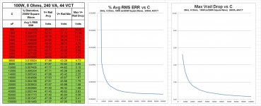
A lot of good stuff to read and understand... (let's hope) Here is some more data, the 100W case to go with the 25W, 50W, and 75W cases in post # 1175, which is at http://www.diyaudio.com/forums/power-supplies/216409-power-supply-resevoir-size-118.html#post3166321 .
I also attached the spreadsheet with all of this. Just remove the .txt from the filename after (or while) downloading it.
It looks like "2500 uF/Amp", using RMS Amps into the load at 2X the maximum rated output power level, would be more than sufficient, for these four 8-Ohm cases, for which the transformer is well over-sized. That gives about 5% as the maximum drop in rail voltage (the drop is relative to its average level), in each case, and about 0.005% average RMS error, in each case, in the square wave that draws 2X the rated power. But you could go as low as 1600-1800 uF per amp, and even lower when rated output power is less than 100W. But for higher than 100W rated output power with the same transformer ratings, more uF/amp would probably be required. I will try to run some other cases, as I get time.
Attachments
Last edited:
No, any electrolytic or solid polymer, OS-CON and the like, will always be safe, even when paralleled with a film cap. Tom doesn't quite agree with me on this, but I suspect the bad behaviours he's come across are because of film caps at a distance from each other, i.e. the lead inductance between the caps comes into play.Tom, @ #1191 and #1200. There are some electrolytics (let's take for example Mundorf MLGO 10000/63) which state low ESR, something like 14 mOhm, so just similar to that of a film cap, and a 20nH ESL.
Any resonation risk around?
Always remember that ESR is not a locked in characteristic, it varies all over the place depending upon just about everything, so don't get hung up on precise values ...
Frank
- Status
- This old topic is closed. If you want to reopen this topic, contact a moderator using the "Report Post" button.
- Home
- Amplifiers
- Power Supplies
- Power Supply Resevoir Size