Houston we have sound..
I have not checked bias..
How to do this?
Stop listening to music through the amp and before you go further with anything, set to appropriate bias current through the output stage and check for output offset.
................ Which one of the big whites is R14 again?... ..............
measure the Vdrop on all of them. Compare the readings to see how good the matching of the source currents are.Measure any of them")
One device that passes more current will run hotter. This could be too much if you run the amp hard.
You should be aiming for the same source current for all the amplifier output devices. That's why you match the resistor resistances and match the output transistors.
EDIT:: Since all of this is quite new for me some basic questions will come from this fellow..
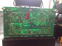
If wee look underneath the board - counting from left to right we got 4 measurepoints. Call them 1-4
A pic is added.
My measurements. (after a bit adjustement)
Right channel:
1 - 21.5mV 2 - 25.8mV 3 - 23.4mV 4 - 23.8mV
Left channel:
1 - 22.1mV 2 - 25.6mV 3 - 22.4mV 4 - 25.9mV
Is this ok or not?... Which value should I settle on...
Attachments
Last edited:
Make r18=1.8k watch your swing into the drivers. Your hum problem could be you might have to lift the input gnd by a 10 ohm resistor. Evette
Hi there. Has anyone experience with this? Lifting the input gnd by 10ohms. What is the meaning of this?
Where in the schematics should a 10ohm resistor be placed then?
http://www.harrisonaudiolabs.com/Amplifiers/SYMEF/SYMEF.pdf
hmm - feels like I have endless with tiny questions
It is natural since this amp plays ridiculously good and I would like to be able to use it with my setup..
So it needs to be hum free and I really need to lower the gain in a way or the other...
Tumbs up soundwis..
Burn in time..It has played about an hour now.. Only new unused components. Can I expect something regarding that issue also?
Attachments
EDIT:: Since all of this is quite new for me some basic questions will come from this fellow..
If wee look underneath the board - counting from left to right we got 4 measurepoints. Call them 1-4
A pic is added.
My measurements. (after a bit adjustement)
Right channel:
1 - 21.5mV 2 - 25.8mV 3 - 23.4mV 4 - 23.8mV
Left channel:
1 - 22.1mV 2 - 25.6mV 3 - 22.4mV 4 - 25.9mV
Is this ok or not?... Which value should I settle on...
Nice Job. The measurements look ok (you can actually see the resistor tolerances in play)
Did you take them after the amp has settled down.
Last edited:
Hi there. Has anyone experience with this? Lifting the input gnd by 10ohms. What is the meaning of this?
Where in the schematics should a 10ohm resistor be placed then?
http://www.harrisonaudiolabs.com/Amplifiers/SYMEF/SYMEF.pdf
hmm - feels like I have endless with tiny questions
It is natural since this amp plays ridiculously good and I would like to be able to use it with my setup..
So it needs to be hum free and I really need to lower the gain in a way or the other...
Tumbs up soundwis..
Burn in time..It has played about an hour now.. Only new unused components. Can I expect something regarding that issue also?
It could be possible the hum is originating from your preamp. Are you using all the devices on one extension cord ? You might consider using separate wall receptacles
Attenuate the input to your preamp, your preamp has humongous gain (some preamps feature adjustable gain or sensitivity control), so cut the signal your feeding it
.
Last edited:
Hi all..
The preamp is silent.. Had Oris horns earlier (108dB senitive) and dead silence when not playing..
What was kind of funny was that I could play on those horns directly from the preamp..
And I am using separate wall receptacles for the Symef.. Reason: the 10A fuse blew when turning on the amp.. Had to use a wall receptacle that had 16A.
The rest of the components are actually fed from an online UPS..
I have also lowered the output from the dac...
However - i Changed from RC to CRC in the psu just now.
Bridge rectifier - 2200uf - 7.5ohm (100w resistor) - 36000uf
Output - 40.5vdc.
Had 35 Vdc with just RC..
Have been playing with the amp some hours now. The initial harshness in the upper regions seems gone. Suspect some burn-in time. Only beautiful music.
I have tried alot of amplifiers during my hifi - time.
This is maybe the first transistor amp I have tested that really grips the woofers and are very dynamic at very low volumes.
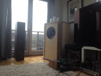
I now use a pair speakers with approx 89-90dB sensitivity for testing purposes. The hum is audible from about 30cm away from the speakers. Not so bad. This might be because of cable mess
I tried to lower R28 from 22k to 7k to reduce the gain. It helped some but not much. I am back to 22k right now.
The preamp is silent.. Had Oris horns earlier (108dB senitive) and dead silence when not playing..
What was kind of funny was that I could play on those horns directly from the preamp..
And I am using separate wall receptacles for the Symef.. Reason: the 10A fuse blew when turning on the amp.. Had to use a wall receptacle that had 16A.
The rest of the components are actually fed from an online UPS..
I have also lowered the output from the dac...
However - i Changed from RC to CRC in the psu just now.
Bridge rectifier - 2200uf - 7.5ohm (100w resistor) - 36000uf
Output - 40.5vdc.
Had 35 Vdc with just RC..
Have been playing with the amp some hours now. The initial harshness in the upper regions seems gone. Suspect some burn-in time. Only beautiful music.
I have tried alot of amplifiers during my hifi - time.
This is maybe the first transistor amp I have tested that really grips the woofers and are very dynamic at very low volumes.
I now use a pair speakers with approx 89-90dB sensitivity for testing purposes. The hum is audible from about 30cm away from the speakers. Not so bad. This might be because of cable mess
I tried to lower R28 from 22k to 7k to reduce the gain. It helped some but not much. I am back to 22k right now.
Last edited:
Hi Bambadoo,
Good to hear your feedback. One suggestion regarding hum, did you get any hum if you power up one amp separately and disconnecting any common connections between the two channels. I feel the hum is coming because of ground loops between the 2 channels.
What's your opinion in the vocals and highs produced by this amp? I listen to classical music through this amp. Strings sound wonderful, lot of air around the instruments vocals are great too. What are your observations with classical music?
Thanks,
Yeah, its always better to check the bias after the voltage changes. My heatsinks are also quite hot, I am thinking of getting bigger ones, with 100mA quiescent current through each output transistor the heatsinks need to dissipate 16W at the idle so I believe your heatsinks are bit under rated for this amp.
Bambadoo, it looks like you modeled your speakers on the Tannoy GRF, which is very efficient design and could be the reason for the amp/pre-amp combination to have too much gain. Obviously you do not want to mess with the pre-amp because it cost you a pack of money so messing with your new power amp is the only alternative.
What you have done is to change the NFB series resistor (22k) to a lower value, don't change the series resistor because you are messing with the amp off-set which could also affect the bias. Rather increase the value of the shunt resistor (to say 3.3k).
Increasing the shunt resistor also offers the opportunity to decrease the capacitor value from 2200uF to much less as it is not necessary to have high near DC gain because it also leads to instability.
Last edited:
Yes I see (i guess...)
I have to get this in small portions... And for me it is easier if it is possible to use parts and numbers that corresponds with the schematic.. Sorry about that..
NFB series resistor = R1 right?
shunt resistor = Rxxx ?
And if I am to do this. Which cap do you mean?
http://www.harrisonaudiolabs.com/Amplifiers/SYMEF/SYMEF.pdf
Sincerely
Yes I see (i guess...)
I have to get this in small portions... And for me it is easier if it is possible to use parts and numbers that corresponds with the schematic.. Sorry about that..
NFB series resistor = R1 right? RIGHT
shunt resistor = Rxxx ? R2
And if I am to do this. Which cap do you mean? C1
http://www.harrisonaudiolabs.com/Amplifiers/SYMEF/SYMEF.pdf
Sincerely
If I were you I would undo one side of R2 from the PCB and wire a 10K potentiometer between R2 flying lead and the PCB. Turn the pot to max. Then adjust your pre-amp to say 3/4 gain and slowly adjust the 10K pot until you are comfortable that you are reaching the SPL levels that you require.
Remove the pot, measure the resistance, add 750 ohms and choose the closest value resistor that you have handy into both channels, as simple as that. Choose a capacitor for C1 that is close to 1/(40 x Pi x R2)
Remove the pot, measure the resistance, add 750 ohms and choose the closest value resistor that you have handy into both channels, as simple as that. Choose a capacitor for C1 that is close to 1/(40 x Pi x R2)
- Home
- Amplifiers
- Solid State
- SYMEF amplifier