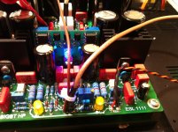
I just upgraded my regulation scheme to this.
The new feature is the 100R resistor between the full earth of the casing and the star ground of the amp - got this from a TI application note that Sonny gave out in his TSSA implementation.
Big thanks 4 that Sonny !
It never occurred to me to include that resistor but upon examination it comprehensively completes the filtration system of this design
Hi mikelm
You can find this 100 ohm resistor on bottom layer of my old SSA PCB (it is also included in new CSA PCB-s). It serves many purposes, one is you mentioned, second it serves to define potential of the heatsink in a testing phase when heatsink is alone, not yet assembled in the case.
")
Attachments
Hi mikelm
You can find this 100 ohm resistor on bottom layer of my old SSA PCB (it is also included in new CSA PCB-s). It serves many purposes, one is you mentioned, second it serves to define potential of the heatsink in a testing phase when heatsink is alone, not yet assembled in the case.
Mike, LC, what if a builder use 2-wire power cord? I think that there are many possibilities with real world implementation (for example you may not know what happen inside your CD player etc), that lead to "uncertainty" in grounding. Even Esperado mentioned that experimenting is still "required" to choose where to connect your center ground.
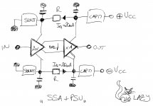
To LC, it would be interesting (i will do on my side if i find time for that) to study a perfect PSU for the SSA. I imagine a combination of serial and shunt regulation, ( with big loss of power expected ;-). Something like common serial and one shunt regulation on each amp board. To see if any noticeable sound improvement.
At this level of quality, no major improvement can be done amp side. PSU can bring the next big step. Don't you think ?
Hi Esperado

Yes, SSA would only gain if PSU is designed and calculated correctly. The aim is still to maintain low PSU serial impedance and reject ripple to voltage gain front-end. A lot more parts to play with but all in a purpose to elevate sound quality.

Attachments
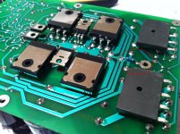
About to connect them. Wish me good.
When I put CCS-s in SSA it went flawlessly, no other adjustments than just correct quiescent current.
It used to be that all metal cased equipment had to be grounded so came always with 3 wire mains leads.
Double insulated designs with plastic case needed only two wire mains leads
But now it is common to see 2 wire mains lead on equipment with with metal case and I do not understand the logic for this.
Can anyone explain this ?
Double insulated designs with plastic case needed only two wire mains leads
But now it is common to see 2 wire mains lead on equipment with with metal case and I do not understand the logic for this.
Can anyone explain this ?
Mike, LC, what if a builder use 2-wire power cord?
Metal case is always in some relation to GND (common input/output potential) no matter if mains earth/neutral potential is or not connected.

Mains earth or neutral potential (depends on installation in the house) should be connected to metal case with zero impedance connection to protect person from possible live potential touching.
My SSA star GND is located on PCB, so only input GND to case connetions and earth meets in one point of the metal case.
This is proven a lot of times, it is not experimental and it works perfectly.
Can anyone explain this ?
Double square sign on the back panel explains that the unit has "double" insulation, so very well protected and because of that there can be only two wires mains connection. No earth loops - interference currents.
Jay,
The signal earth connection that comes out of your source has to be connected to your star earth point ( or to star earth via small R typically 10R ) not much choice in this.
As I mention above often consumer sources are not grounded so in some ways this makes life simple.
You could use a 2 wire lead on your amps but it would be much safer to use 3 wires and ground the metal casing / heatsinks. The 100R resistor LC refers to above eliminates my concerns about connecting a "dirty" domestic earth to my nice clean system ground.
But of course if you want the entire system ground to be clean, you will have to make sure that all equipment connected to it has similar elegant earthing arrangement.
Not sure if that answers your question.
mike
When I put CCS-s in SSA it went flawlessly, no other adjustments than just correct quiescent current.
Same here. Just connected the mirrors and ran the amp. It went as if nothing has been changed. The total Iq has decreased about 20mA(at 160mA, before was 180-185). I set the offset and immediately played some music.
This is AWESOME. BIG change in the stuff that's coming from the speaker. It gave me goosebumps haha. The whole soundstage has gotten bigger, it felt like the speaker isn't 4" any more, it's a 8 inch one. Marvelous! WOW. Clean - Clear.
But.
1. Noise. Yes there is audible white noise. Not audible with music, but as soon as the music stops, hissss.s.ssss.ss.s.sss.s. I read in the net that this would happen to wilson, a curse.
2. Offset. Wow this Wilson is quite a drunken dude. It just can't control itself, keeps sliding between +-200mV randomly. I expected this, but hope this can be solved.
How to kill that damned HISS?
Same here. Just connected the mirrors and ran the amp. It went as if nothing has been changed. The total Iq has decreased about 20mA(at 160mA, before was 180-185). I set the offset and immediately played some music.
This is AWESOME. BIG change in the stuff that's coming from the speaker. It gave me goosebumps haha. The whole soundstage has gotten bigger, it felt like the speaker isn't 4" any more, it's a 8 inch one. Marvelous! WOW. Clean - Clear.
CCS cause modulation of input/feedback BJT to be independent from Rinject voltage drop, so really purified, lot less THD.
But.
1. Noise. Yes there is audible white noise. Not audible with music, but as soon as the music stops, hissss.s.ssss.ss.s.sss.s. I read in the net that this would happen to wilson, a curse.
How to kill that damned HISS?
Hiss is always oscillation, so scope into action, readjust Cm.
CCS makes greater bandwidth, previous Cm is not suitable for new conditions anymore.
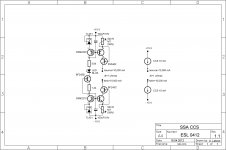
It can be solved only with some thermal independent Vref like TL431 etc. That's why mine CCS are like sch on the pic.But.
2. Offset. Wow this Wilson is quite a drunken dude. It just can't control itself, keeps sliding between +-200mV randomly. I expected this, but hope this can be solved.
Attachments
Last edited:
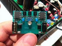
Matched BJT mirrors in DIP (SSM parts), cascodes are fets, TL431 in TO-92.Very nice looking. What is the one in DIP8? TLC431?
These CCS works in SSA which is in mastering studio and the sound is very good, as confirmed by mastering engineer and many musicians. Shaan, I spent quite some time to find, choose and implement the best CCS into SSA, considering DC + thermal stability, AC performance, Iccs modulation suppression and noise level. Schematic I showed you is all that.
SSM matched pair serves to copy TL431 2,5 V into trimmer without Vbe thermal influence as well as noise performance of this chip laser trimmed pair.
TL431 is also very thermally stable regarding price/performance and last but not least fet cascodes puts Iccs modulation suppression down to -100 dB as I measured up to 100 kHz. All in all very good CCS performance.


Not sure if that answers your question.
My main point was that there are many possibilities with everyone's grounding environment, such that a partial solution may not work best with different environment.
There are many schemes for grounding, and I think a grounding scheme must be an integral solution not partial. But often, people only take a few parts from one scheme and a few other from another scheme.
In your grounding case with 100R, my question was, will there any chance that shorting the resistor will be much better when there is no earth connection to the chassis? This is not my environment/situation of course.
The signal earth connection that comes out of your source has to be connected to your star earth point ( or to star earth via small R typically 10R ) not much choice in this.
There are many real life situations/implementations where this 10R doesn't improve but make things worse. I mean, this is an experience of many people. If it is always good, then every circuit will use it, which is not the case.
One very old scheme but proven effective I think is the one suggested by Esperado. I build my grounding scheme simply from understanding where the currents will flow (which points have higher potential than others). The bigger current is always in the amplifier, and in the output stage capacitor.
More difficult is solving the problem caused by interference or couplings. Existence of switching device will affect decisions.
Every houses have different power line quality, and also different earth ground quality. Many audiophiles improve the quality of their grounding, because good one requires expensive copper? How bad the surroundings is, will affect decision (Note: the grounding issue has close relationship with power supply). That is when the decision (EDIT: solution) has a possible drawback (the cure might be worse than the disease).
Last edited:
- Status
- This old topic is closed. If you want to reopen this topic, contact a moderator using the "Report Post" button.
- Home
- Amplifiers
- Solid State
- Simple Symetrical Amplifier