Definition of IM and TIM. (will be hard with my poor English)
IM is produced when a little level high frequency is 'modulated' by a lower frequency. A little like when you play two guitar cords not exactly in tune, see what i mean ?
TIM is produced when the Amp is not enable to follow a fast change of level. (not enough slew rate). A little like if he produce IM between the signal he is able to follow and the upper harmonics of it he is unable to follow.
In those two cases, the IM is an added signal which can be out of the Xn of the fundamental frequency. Not harmonics. Our ears analyses-it as an other source of sound that the original signal. Mud, not painting. Since, when it is harmonic, our ears percieve-it as the same source, with a slightly different color.
Of course, mikelm, if you get an amp with bad IM, it will produce IM with the high harmonics of a signal as well as added noise. And, of course, if you reduce those noises and parasitic signals, you will decrease IM. But you are curing the symptoms, not the disease.
See what i mean ?
That is why it is always a prerequisite to filter the signal, at the in of an amp or a preamp for it never have to deal with signals faster than those it can follows.
About phase, we have to clarify too. You know that acoustic distance from source change the relative phase of the frequencies. The delay due to sound transmission in air will not change the phase of the very low frequencies (because the delay length will be little comparing to the wave length), while high frequencies will be hardly affected.
Our ears do not care. What is important is the constant and regular correlation between those phase, called 'Group delay".
Improper aligned loudspeakers, as an example, destroy the group delay witch have to be as flat as possible. That's some people are using digital filters and delays to correct their loudspeaker's group delay, with great benefit.
Mesures de miniMaX (sorry, it is in French).


Oh, my god, i hope i'm not boring everybody here, talking like an old school teacher. If yes, please, let me know.
As a thread starter I welcome your contribution to each and every detail, since you're true man from the professional audio circles, having rich R&D experiences from commercial audio production company, plus you're DIY expert and CFB fan. What can I say, we need you here man.

LC, by CSA, do you mean this? Or some other beast?
Maybe this will help:
http://www.diyaudio.com/forums/soli...est-symmetrical-amplifier-88.html#post3111266
"There's no CSA thread yet, only CSA amp itself in assembly phase. Will start the thread when ..."


LC, by CSA, do you mean this? Or some other beast?
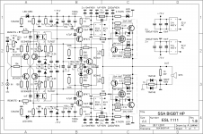
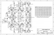
I like the simplest versions of SSA and TSSA, they all produce nice sound, but Lazy Cat wouldn't be satisfied if not checked what's max performance one can get out from this topology. So logical step is slowly but gradually to go to high performance (HP) versions of them all. Continuous learning process progresses as you can see if carefully follow the threads, many solutions appeared on the way, which were tested and implement by individuals. Many of you experimented and adopt different variants based on common SSA CFB topology, very nice evolution happened since the start. Sonny is the first who's successfully managed to start group buy of his version of TSSA amp, offering best info, PCB's, parts, manuals, we all others are still searching ...
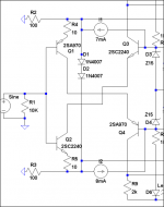
Sch from your post is SSA BIGBT HP before applying CCS, than TSSA BIGBT HP came (pic) which will be soon build by Marc (Idefixes) and than I extend this one to CSA sch which is now in testing phase. CSA stands for Complex Symmetrical Amplifier, which name explains itself. VAS is packed with semis: 22 transistors, 7 reference zeners, etc. Output is of course my preferable BIGBT. Looking to TSSA BIGBT HP can give you an impression where to CSA is evolved onward.
")
Attachments
Update:
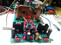
After letting SSA with the new CCS run without signal for a whole night I checked the offset and bias after waking up in the morning. Unchanged.
Yeppee! Feels like an achievement!


Hehe... I'm just happy LOL.
Thanks Andrej and all.
That's the way I like it (KC&SB) hehe
After CCS implementing, you're probably more satisfied with the sound than before with only current injection resistors, true?
Now these SSA modules deserves a nice DIY case-home, don't you think?
Regards, Andrej

Attachments
I like the simplest versions of SSA and TSSA, they all produce nice sound, but Lazy Cat wouldn't be satisfied if not checked what's max performance one can get out from this topology. So logical step is slowly but gradually to go to high performance (HP) versions of them all. Continuous learning process progresses as you can see if carefully follow the threads, many solutions appeared on the way, which were tested and implement by individuals. Many of you experimented and adopt different variants based on common SSA CFB topology, very nice evolution happened since the start. Sonny is the first who's successfully managed to start group buy of his version of TSSA amp, offering best info, PCB's, parts, manuals, we all others are still searching ...
Sch from your post is SSA BIGBT HP before applying CCS, than TSSA BIGBT HP came (pic) which will be soon build by Marc (Idefixes) and than I extend this one to CSA sch which is now in testing phase. CSA stands for Complex Symmetrical Amplifier, which name explains itself. VAS is packed with semis: 22 transistors, 7 reference zeners, etc. Output is of course my preferable BIGBT. Looking to TSSA BIGBT HP can give you an impression where to CSA is evolved onward.
GREAT!!!
That's the way I like it (KC&SB) hehe
After CCS implementing, you're probably more satisfied with the sound than before with only current injection resistors, true?
Very true.
Now these SSA modules deserves a nice DIY case-home, don't you think?
Regards, Andrej
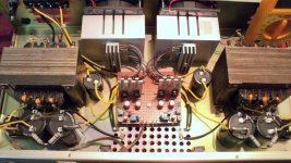
Not this one. This will probably just be there in its naked phase for enjoyment, experiment and learning. I learned a LOT and am still learning and want to learn more.
The one that will go into a metal case is another pair of SSA on a larger board(veroboard of course
) for one of my friends who lives about a thousand km away but was present here with me while I had just finished the resistor-feed SSA. His jaw just dropped down to his feet when SSA played music and after 11 days of audition he said I must build one just like that for him. Delivery will be in December or new year. His presence helped me a lot in determining the truth about SSA sound. He used to listen to it almost all the time with a smile and often went to sleep during listening, at quite high volume. I was assured that SSA is indeed different and better than usual market stuff.
Last edited:
Nice job Shaan, congrats.
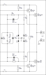
Depletion mode two terminal CCS in the form of BF245C JFET or Supertex DN2540 TO-92 MOSFET (Sheldon) were effective enough, and as far as simplicity and compactness goes, handy. We added them some time ago if looking rather far back in this thread. Trimmers for their source pin degeneration can give current control, and they can be added easily on main test board of course. Your ring of two BJT CCS is maybe better tracking the input pair junctions and worth the extra boards though, quite possibly. Talking about those same positions, the ones injecting to the input pair emitter feedback summing resistors (I1&I2), right?
Depletion mode two terminal CCS in the form of BF245C JFET or Supertex DN2540 TO-92 MOSFET (Sheldon) were effective enough, and as far as simplicity and compactness goes, handy. We added them some time ago if looking rather far back in this thread. Trimmers for their source pin degeneration can give current control, and they can be added easily on main test board of course. Your ring of two BJT CCS is maybe better tracking the input pair junctions and worth the extra boards though, quite possibly. Talking about those same positions, the ones injecting to the input pair emitter feedback summing resistors (I1&I2), right?
Attachments
Salas..
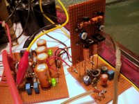
What are the two Diodes D1-D2.. for..?? thermal..??
One reason for the BIG improvement with CCS, is that the current injection from the feedback modulate the current running the circuit, The signal simply alter the working condition of the circuit. this is not the case with the CCS solution where this mechanism is taken out...
Salas..
What are the two Diodes D1-D2.. for..?? thermal..??
One reason for the BIG improvement with CCS, is that the current injection from the feedback modulate the current running the circuit, The signal simply alter the working condition of the circuit. this is not the case with the CCS solution where this mechanism is taken out...
The diodes are those two to help open the power LatMosfet gates equally, just drawn to the other side, same nodes, see them again in Nico's.
Yes current modulation, that is the reason why TSSA came about also. Will be interesting to hear what does it better, DC to ground FB, Sziklai source follower 175mA, or AC to ground FB, emitter follower and common source 0.6A, already got a pair of Sonny's SMT boards to make one.
Attachments
That's right Salas.
The two bjt CCS proved to be reliable, both in current supply stability and thermal independence. I also has extremely low noise, I can hear the noise only with an ear-over-speaker test.
Ring of two is trusty, one of the stablest simple ones. I use it many times too. I had measured bandwidth extension by 25% when I had applied the JFET sources, you should got some of that too, if by any tell tale sonic clue.
- Status
- This old topic is closed. If you want to reopen this topic, contact a moderator using the "Report Post" button.
- Home
- Amplifiers
- Solid State
- Simple Symetrical Amplifier