GU50 PP
Triode connected GU50 push-pull amplifier with EL34 single ended driver stage.
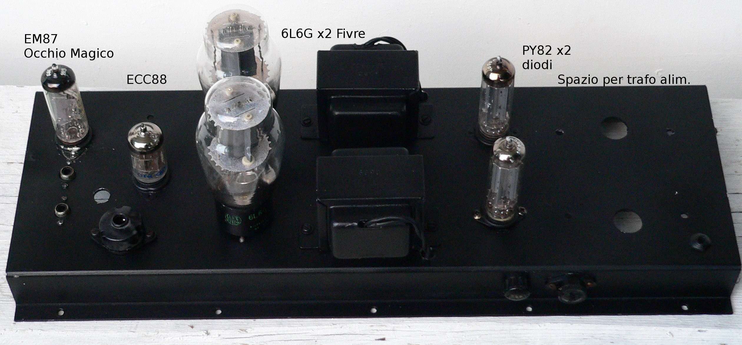
The empty sockets are for magic eyes (EM87/6E2/6HU6) monitoring the power output:
Something like this:
Pics from building the first mono block earlier this summer:
Empty chassis:
Soldering:
Triode connected GU50 push-pull amplifier with EL34 single ended driver stage.
An externally hosted image should be here but it was not working when we last tested it.
The empty sockets are for magic eyes (EM87/6E2/6HU6) monitoring the power output:
An externally hosted image should be here but it was not working when we last tested it.
Something like this:
An externally hosted image should be here but it was not working when we last tested it.
Pics from building the first mono block earlier this summer:
Empty chassis:
An externally hosted image should be here but it was not working when we last tested it.
Soldering:
An externally hosted image should be here but it was not working when we last tested it.
Thanks zman.Thanong,
The Tubelab Simple SE or SSE is a design done by George Anderson aka Tubelab. Tubelab Home. You can get the circuit design at his site, or opt for the PCBs he also has.
Tipetu,
Looks nice - I am thinking of something along similar aesthetic for a Tubelab PP project.
Triode connected GU50 push-pull amplifier with EL34 single ended driver stage.
An externally hosted image should be here but it was not working when we last tested it.
Pro job Jan

Did you make a PSU compartment?
Extra sleeving on the HT wires?
He kept the GU50s out of view. Smart move.
Keep out of the way ,no way
.Mine are going to be right up front .With their tube caps on top and their caged ceramic base's
Cheers
Last edited:
To thanong, I`m thrilled you would like to build a similar amp. I`ll have to admit, I really liked the idea of hiding the choke and remove the big eyecatching can-capacitor. So I did!
Tore it all apart. Filled the holes in the chassis with JB-weld followed up with bondo and lots of sanding. It came out fair enough I think. Good enough for me! This is a everyaday amp. Not showroom quality!
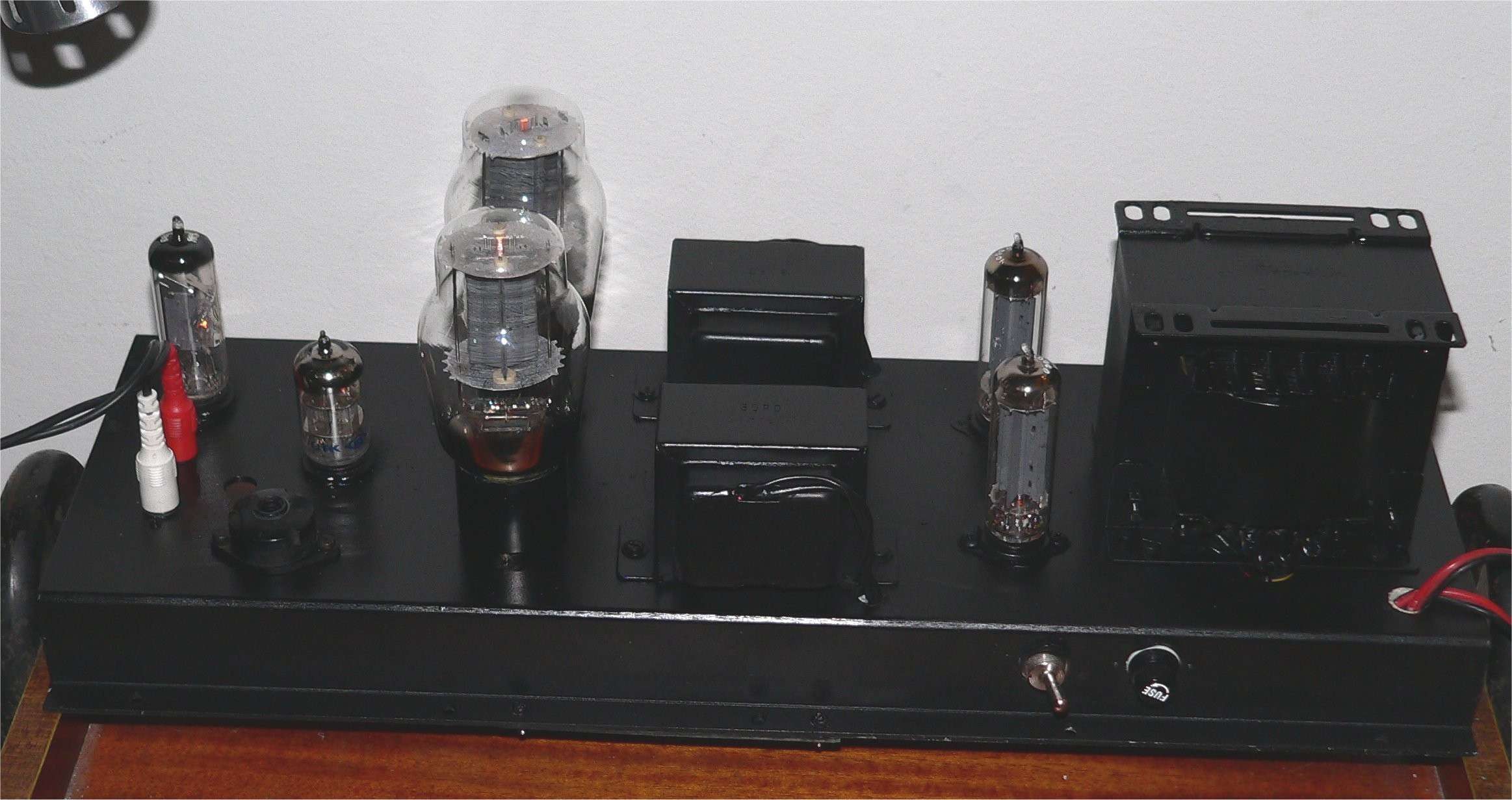
This is the "new look"
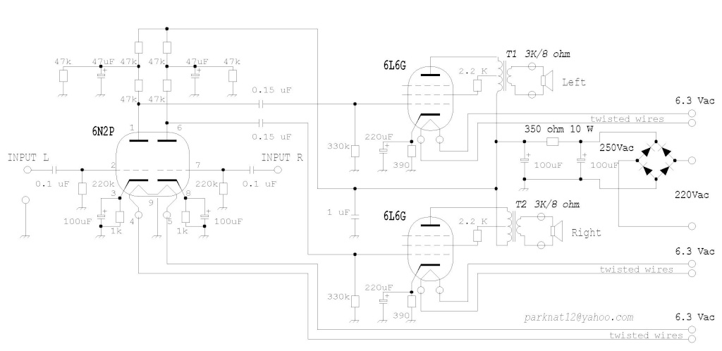
And as promised, the schematic. If you have any questions, do not hesistate to ask.
Tore it all apart. Filled the holes in the chassis with JB-weld followed up with bondo and lots of sanding. It came out fair enough I think. Good enough for me! This is a everyaday amp. Not showroom quality!
This is the "new look"
An externally hosted image should be here but it was not working when we last tested it.
And as promised, the schematic. If you have any questions, do not hesistate to ask.
An externally hosted image should be here but it was not working when we last tested it.
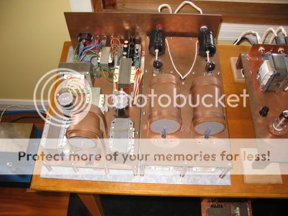
Why would you spray caps? Esthetics?
Yes , I didn't like the look of the poly/prop Solens ,so they got the copper treatment
.
CHeers
Yeah, the choke looked "untidy". Why would you spray caps? Esthetics?
Now I got it, You meant painting the can-capacitors. I was thinking painting the small signal capacitors
Take care with coopercover caps, is a filter for bass frequency and you can lose high tones.
Thanks for the heads up
. So far I haven't heard any losses .My tech mate tested the dac and also found no issue .I ran what i wanted to do pass him before I done it. The caps are in the power supply .56oval: which part of Australia are you from? How do you apply the copper?
From Vic , its a foil wrapped around the cap with a swage fold underneath .I allowed 3 mmm over hang on the edge's then carefully folded the edges over no to crease to much .
Cheers
Hi Tipetu,thanks a lot for diagram.I will try.To thanong, I`m thrilled you would like to build a similar amp. I`ll have to admit, I really liked the idea of hiding the choke and remove the big eyecatching can-capacitor. So I did!
Tore it all apart. Filled the holes in the chassis with JB-weld followed up with bondo and lots of sanding. It came out fair enough I think. Good enough for me! This is a everyaday amp. Not showroom quality!
This is the "new look"
An externally hosted image should be here but it was not working when we last tested it.
And as promised, the schematic. If you have any questions, do not hesistate to ask.
An externally hosted image should be here but it was not working when we last tested it.
Take care with coopercover caps, is a filter for bass frequency and you can lose high tones.
May I ask, why?
May I ask, why?
Yes you can ask.
The coper layers connected to ground in capacitors in the audio signal chain was an old technique for isolate from hum and other parasitic in purist audio devices. In those times the impedances were so high, because were expensive use high value and quality capacitors. Probably with high impedances every parasitic capacitance was transcendent to act like bass pass filter. And I heard at 13th age in avoid this technique (I were building a push pull amp with 6BQ5)
Now when I answered your message I made a better read of the whole story and must reflexionate my counsel about the coper over the caps.
Thank you! I was asking because I have some capacitors similar to those, and I have them actually grounded.Yes you can ask.
The coper layers connected to ground in capacitors in the audio signal chain was an old technique for isolate from hum and other parasitic in purist audio devices. In those times the impedances were so high, because were expensive use high value and quality capacitors. Probably with high impedances every parasitic capacitance was transcendent to act like bass pass filter. And I heard at 13th age in avoid this technique (I were building a push pull amp with 6BQ5)
Now when I answered your message I made a better read of the whole story and must reflexionate my counsel about the coper over the caps.
http://www.tnt-audio.com/jpeg/audionotecaps.jpg
- Home
- Amplifiers
- Tubes / Valves
- Photo Gallery