Over the last couple days I built my first Paraline using 6.35mm wood. (All of my other Paralines used Luan (sp?), which is 5mm)
Switching to 6.35mm really nuked the output above 16khz; it's been reduced by about 6dB at least, while using a compression driver that routinely goes to 20khz. (Celestion CDX1-1425.)
Just something to look out for if you try and build these; the height of the line really seems to set a steep limitation on high frequency output.
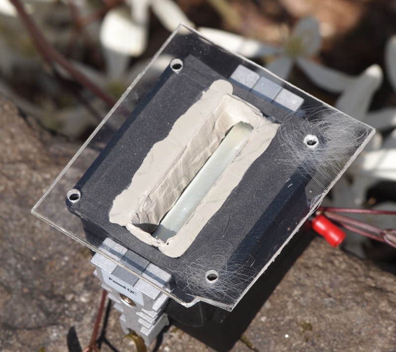
Have been tempted to drive over to Tap Plastics and try to make one out of plexiglass, I think that might simplify lining up all the devices, plus it would look rad")
Geddes uses plexiglass to line up compression drivers on his waveguides, and I copied that trick with some ribbons a few months ago. Works really nice.
Switching to 6.35mm really nuked the output above 16khz; it's been reduced by about 6dB at least, while using a compression driver that routinely goes to 20khz. (Celestion CDX1-1425.)
Just something to look out for if you try and build these; the height of the line really seems to set a steep limitation on high frequency output.
Have been tempted to drive over to Tap Plastics and try to make one out of plexiglass, I think that might simplify lining up all the devices, plus it would look rad
Geddes uses plexiglass to line up compression drivers on his waveguides, and I copied that trick with some ribbons a few months ago. Works really nice.
Patrick,Over the last couple days I built my first Paraline using 6.35mm wood. (All of my other Paralines used Luan (sp?), which is 5mm)
Switching to 6.35mm really nuked the output above 16khz; it's been reduced by about 6dB at least, while using a compression driver that routinely goes to 20khz. (Celestion CDX1-1425.)
Did going from 5 mm to 6.35 mm drop output by 6 dB @16 K, or is the 6.3 mm Paraline down 6 dB @ 16 K from a "normal" horn?
weltersys,
I think what Patrick is saying that compared to his earlier design with the thinner cross-sections that the high frequency roll off was that severe. I am just watching this thread, I am not a big fan of these designs but I see what seems to be going on here. What I think is happening is that the Paraline is acting as a resonant trap that is tuned by the different dimensions of the folds. By changing the height of the sections you have increased the filtering or trapped the upper frequencies by setting a resonant trap at this particular frequency and anything above is attenuated. I would think if you decreased the cross-sectional height that just the opposite function would occur and the upper frequency output would increase but probably at a cost of the lower frequencies due to increased restriction. It looks like you are adjusting a band pass filter in this section. I will wait to see what Patrick or someone else says about this. I am only making these observation thinking about how I believe this folding mechanism is functioning.
Steven
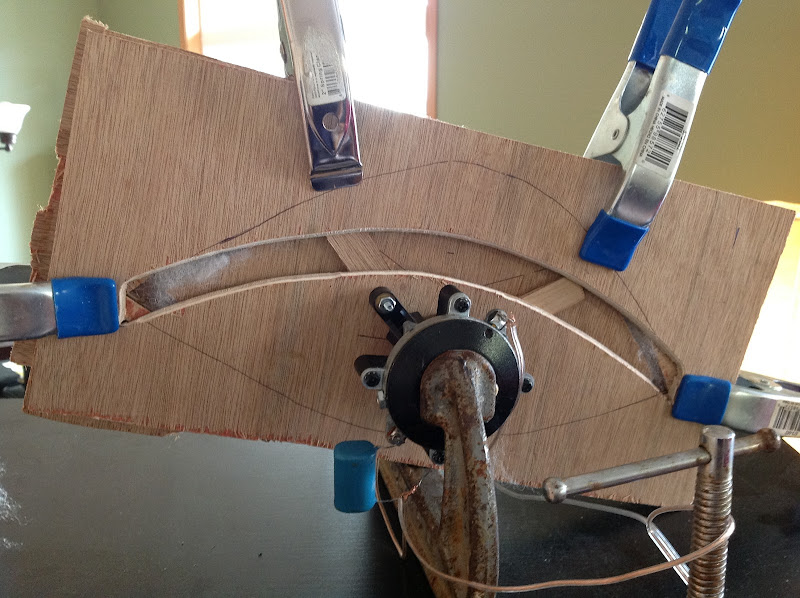
These things are so easy to build, I say just dive in and make one. No need to make this too complex. If you can live with a flat wavefront, then cut five pieces of wood and make each piece twice as tall as it is wide. Draw the 'eye' by hand. Array the driver(s) around the center. Make the mouth about 2cm wide, and as tall as the long end of your wood.
Boom! You got a Paraline.
Humor me and post videos of it plz
Now you've done it. Cheapie drivers ordered.
Will report back on my shenanigans soon. onebadmonte,
Your last statement is one that I just can't understand or abide by. Just because this construction seems so simple why would you or anyone think that this would make a cheap device sound good. A poorly designed device with poor frequency response is not going to be improved by this loading scheme, that doesn't make any sense at all. You may be band limiting some of the extreme problems of the driver but they are still there and will be in the end. I see all these people talking about using cheap poor devices and I wonder where they think the magic is that is going to fix them? A terrible sounding compression driver will still sound terrible and have the same problems it has had all along. What I believe is even with this device is that thoughtful design would improve the accuracy of the frequency response and haphazard dimensions will only make the frequency response that much more ragged. I have already thought of some major way to improve this design but they would be much more difficult to produce. This follows with the design of any and all waveguides, there is no free lunch......
Your last statement is one that I just can't understand or abide by. Just because this construction seems so simple why would you or anyone think that this would make a cheap device sound good. A poorly designed device with poor frequency response is not going to be improved by this loading scheme, that doesn't make any sense at all. You may be band limiting some of the extreme problems of the driver but they are still there and will be in the end. I see all these people talking about using cheap poor devices and I wonder where they think the magic is that is going to fix them? A terrible sounding compression driver will still sound terrible and have the same problems it has had all along. What I believe is even with this device is that thoughtful design would improve the accuracy of the frequency response and haphazard dimensions will only make the frequency response that much more ragged. I have already thought of some major way to improve this design but they would be much more difficult to produce. This follows with the design of any and all waveguides, there is no free lunch......
Patrick,
Did going from 5 mm to 6.35 mm drop output by 6 dB @16 K, or is the 6.3 mm Paraline down 6 dB @ 16 K from a "normal" horn?
Jury is still out - my measurement system is anything but elite. But it seems like going from a Paraline with an internal height of 5mm to one with a height of 6.3mm really rolled off the output above 16khz. (same compression driver on both)
Another possibility is simply that my woodwork is too sloppy. (Having said that, the 5mm Paralines were even sloppier, and they had significant output above 16khz)
Danley's 'rule of thumb' is that the internal height of the Paraline should be set to no more than one third of the highest wavelength. For instance, an internal height of 0.5cm should get you to 22,666hz. Perhaps it's more like one quarter wavelength? That would indicate an upper limit of 17khz for an internal height of 0.5cm.
Again, jury is still out on this. It may be poor workmanship. I've also noticed that there seems to be a correlation between Paraline size and high frequency output.
Patrick,
I think that you just discovered what I said earlier. The height is acting as a frequency trap and the 1/4 rule applies in every instance of waveguide design that I have ever done. If you decrease the distance or thickness of the cross-sections below the 0.5 cm and leaving all else the same let's see if the high frequency doesn't get over the 17khz figure you sighted. What I am wondering is what is happening on the other extreme at the lower frequency leaving the final mouth size and cutoff the same. I would bet that you are increasing the Q of the horn and the response curve will have an increase in the middle of the band. I also wonder if your compression driver even has any real output in the upper frequencies, this is a standard issue with almost every compression driver. Most 1" drivers start to turn down by about 12Khz and fall from there.
I think that you just discovered what I said earlier. The height is acting as a frequency trap and the 1/4 rule applies in every instance of waveguide design that I have ever done. If you decrease the distance or thickness of the cross-sections below the 0.5 cm and leaving all else the same let's see if the high frequency doesn't get over the 17khz figure you sighted. What I am wondering is what is happening on the other extreme at the lower frequency leaving the final mouth size and cutoff the same. I would bet that you are increasing the Q of the horn and the response curve will have an increase in the middle of the band. I also wonder if your compression driver even has any real output in the upper frequencies, this is a standard issue with almost every compression driver. Most 1" drivers start to turn down by about 12Khz and fall from there.
Patrick,
I think that you just discovered what I said earlier. The height is acting as a frequency trap and the 1/4 rule applies in every instance of waveguide design that I have ever done. If you decrease the distance or thickness of the cross-sections below the 0.5 cm and leaving all else the same let's see if the high frequency doesn't get over the 17khz figure you sighted. What I am wondering is what is happening on the other extreme at the lower frequency leaving the final mouth size and cutoff the same. I would bet that you are increasing the Q of the horn and the response curve will have an increase in the middle of the band. I also wonder if your compression driver even has any real output in the upper frequencies, this is a standard issue with almost every compression driver. Most 1" drivers start to turn down by about 12Khz and fall from there.
Haha I am a tool.
It looks like one of the reasons that I'm losing output in the top octave is because the midrange is playing much higher than I'd expected.
Here's an example of this. Let's say you have a midrange diaphragm that's 10cm away from our compression driver diaphragm. If both diaphragms are radiating 2000hz, then they can be about 4.25cm apart before the pathlength difference begins creating problems. (The formula is [speed of sound / pathlength / 4]
But by 8khz, our margin of error is 1.0625cm! And by 16khz, it's a fraction of a centimeter!
So - long story short - I'm a tool
It's likely not the height of the line that's hosing me up here, it's likely the very extended response of the 2" midranges that I'm using in my Paraline. They're creating a mess of comb filtering above the point where they're more than 1/4 wavelength apart, or about 1900hz or so.
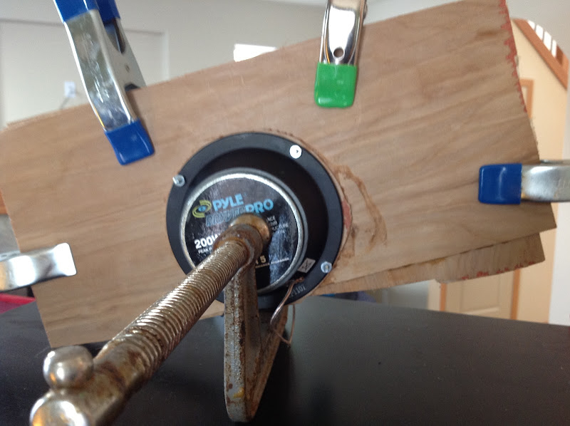
The reason that the other Paraline didn't suffer from this problem was because I was using the Pyle 5" midrange, which does not play as high at all. It has a treated cone, AND it's larger, AND it has more inductance.
One thing about the Paraline which is a bit mystifying is that the sound does not radiate until it reaches the mouth but that doesn't mean that the pathlength doesn't matter. This was one of the things that sorta made my head explode when I first realized it, the idea that you could have a midrange and a tweeter that aren't even radiating sound, but you still have to be conscious of driver geometry. (IE, even if the duct is too small for the wave to form, there's still an inherent time delay due to pathlength differences.)
In fact, I'd argue that you have to be MUCH MORE conscious of driver geometry in a Paraline than in a conventional horn, or on a flat baffle. For instance, let's say you have one of the Lambda Unity horns. It has a coverage angle of sixty degrees. At the point where the midranges tap into the horn, the energy radiated by the compression driver is already covering about one hundred square centimeters. I have a feeling that this would minimize comb filtering to a degree. The worst case-scenario for comb filtering would be a situation where you have two drivers that are more than 1/4 wavelength apart, *and* they're radiating the same energy, *and* that energy is constrained into a duct where the radiation is very intense. Like in a Paraline
Last edited:
Patrick,
Please turn off the midrange drivers and then tell me what the frequency response of only the compression driver is alone on the different thickness sections does. This is the effect that I want to see, not the interaction of the two devices after combining. I want to know what the actual folded section is doing with the variation in thickness.
Please turn off the midrange drivers and then tell me what the frequency response of only the compression driver is alone on the different thickness sections does. This is the effect that I want to see, not the interaction of the two devices after combining. I want to know what the actual folded section is doing with the variation in thickness.
To actually do a valid comparison would also requiring covering up the mid range exit ports, as they will allow some amount of HF energy in, which will take a longer time to come out (unless it is absorbed, in which case it is lost output) than the rest of the HF driver's output, also contributing to HF loss or peaked response.Patrick,
Please turn off the midrange drivers and then tell me what the frequency response of only the compression driver is alone on the different thickness sections does. This is the effect that I want to see, not the interaction of the two devices after combining. I want to know what the actual folded section is doing with the variation in thickness.
That said, for a quick comparison, shorting the mid drivers out while testing the HF will get part way there in determining what is causing the HF loss.
The high frequencies above 14,500 Hz or so in my Paralines using 1/4" gap (about 6mm) roll off at a steeper rate than using a standard conical expansion horn with the same driver.
Art
Art,
Thank you. I understand completely what you are saying the cavities and the cones would act as filters and affect the final output. I guess you could just remove the drivers and put a plate over the mid exit holes, you would still have some cavity resonance in the cavities though they would be rather shallow, I am just trying to see the effects of the actual folded sections. I understand what the waveguide after the paraline is going to do so I am not trying to discuss that portion. Just the throat transition form the driver to the waveguide connection.
Steven

Patrick,
Please turn off the midrange drivers and then tell me what the frequency response of only the compression driver is alone on the different thickness sections does. This is the effect that I want to see, not the interaction of the two devices after combining. I want to know what the actual folded section is doing with the variation in thickness.
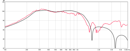
We can't make an 'apples to apples' to comparison, but we can get close. I've built Paralines which are relatively similar in size and shape, except one is taller internally than the other. (One is 0.5cm internally, the other is 0.635cm.)
I still hold to my hypothesis, which is that most of the comb filtering in my new Paraline is due to the interaction between the small midranges which I favor.
Here is the data.
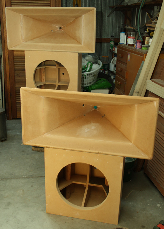
I'd say that this is the best-sounding Paraline that I have built so far. It measures about 40cm by 20cm. (The wood is bigger, but the internal Paraline measures about 40cm by 20cm.)
One really oddball aspect of this Paraline is that the compression driver enters on one side, and the midrange enters on the other.
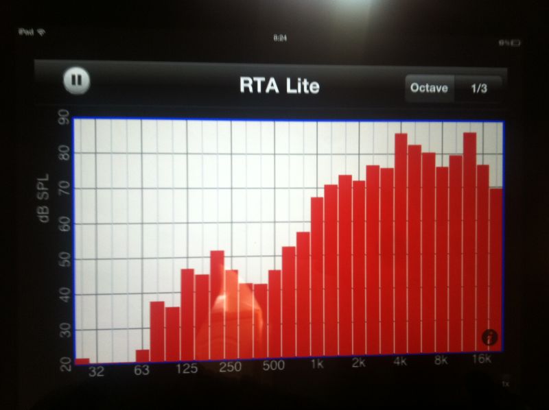
here is the output of the compression driver

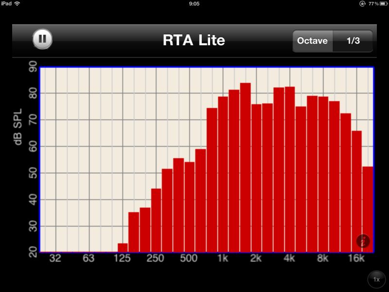
Here is the output of the midrange. I think that this graph is particularly impressive. There's no filter at all on the midrange, and we have an almost picture-perfect 12dB/octave rolloff. This makes it very very easy to cross over to a tweeter.
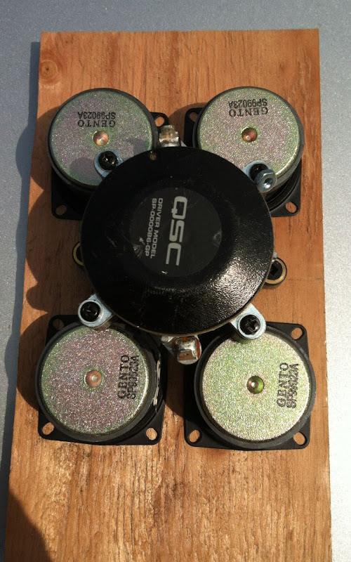
This is my latest Paraline. It uses the same compression driver, but swaps out the Pyle mids for a quad of the buyout 5cm drivers from PE. (Same ones that Bill Waslo uses for his Synergy horn.) The Paraline measures 22cm x 11cm.)
Here's the output of the compression driver on the new Paraline. See how it's output at the very top is down by 28dB, versus about 10dB for the Paraline that's shallower?

Here's the output of the midranges. As you can see, there's MUCH more output above 2khz. For instance, the Pyle is attenuated by nearly 40dB at 8khz, versus just 15dB of attenuation for the Gento SP990223A woofer.
In summary:
1. I believe that hornresp underestimates how much high frequency output is generated by the midranges. I think this is because Hornresp simulates the midranges as if they were a perfect piston, and in the real world, there's a lot of additional factors that computer sims don't show us. Basically, small midranges have more output than the sims would lead you to believe
2. I believe the face-to-face coupling of my Pyle Paraline has some intersting advantages. Getting the drivers coincident on a Paraline solves a lot of problems. If you took it to the next level, it would look like this:
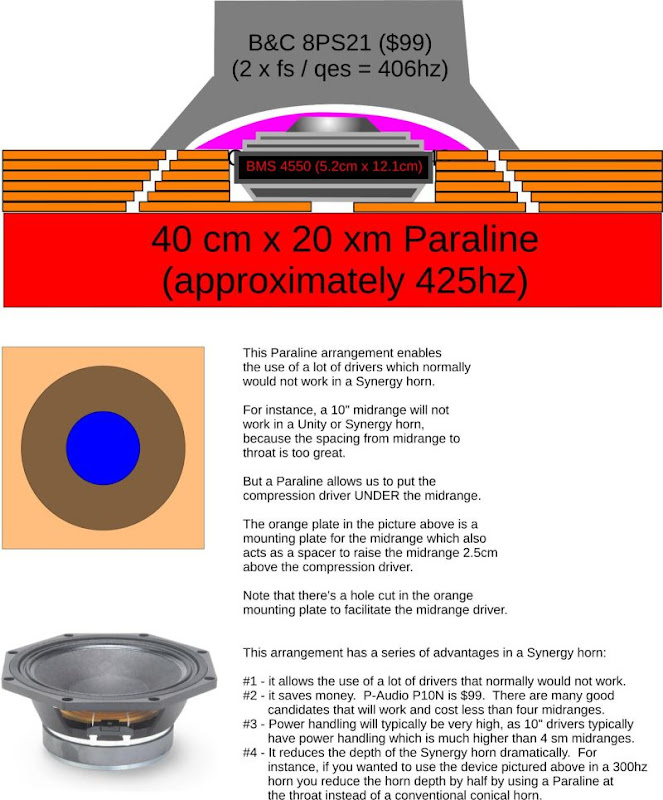
For comparison's sake, here's Paul Spencer's PDMR5 on his synergy horn, with the simulated versus measured response:
Here is my PDMR5 on a Paraline:
IMHO, Paul is getting output down to 200hz because he has a horn that can load it. (You'd want a horn with a depth of approximately 42.5cm to get output down to 200hz.) My Pyles are clearly crapping out a lot sooner, but the Paraline is still loading it down to about 425hz. And, of course, the footprint is dramatically smaller on the Paraline.
Obviously, my #1 reason for using these things is that they allow for a form-factor that's just ridiculously small for a horn of a given cutoff.
onebadmonte,
Your last statement is one that I just can't understand or abide by. Just because this construction seems so simple why would you or anyone think that this would make a cheap device sound good. A poorly designed device with poor frequency response is not going to be improved by this loading scheme, that doesn't make any sense at all. You may be band limiting some of the extreme problems of the driver but they are still there and will be in the end. I see all these people talking about using cheap poor devices and I wonder where they think the magic is that is going to fix them? A terrible sounding compression driver will still sound terrible and have the same problems it has had all along. What I believe is even with this device is that thoughtful design would improve the accuracy of the frequency response and haphazard dimensions will only make the frequency response that much more ragged. I have already thought of some major way to improve this design but they would be much more difficult to produce. This follows with the design of any and all waveguides, there is no free lunch......
I completely disagree with your assessment that expensive or elite drivers must be used to get a high performing speaker system. On multiple occasions I have proven just the opposite can be true. ( See below examples) It all depends on the choice of the delivery device. Horns, wave guides, tapped horn, Unity, Synergy, paraline, or any other device have different requirements to obtain the best performance. It just so happens that inexpensive sealed back mids have the right set of parameters to make several of these devices work. What might be considered a deficient performance attribute can be transformed into an asset depending on the delivery device. I agree there is no “free lunch”. What you have failed to see is we are “paying our dues” by utilizing an innovative device and making engineering choices. You cannot make a blanket statement that inexpensive drivers will result in poor performance. Just look at the driver choices that Danley Sound has made. No one here can say with a straight face that Danley's products are junk because he uses inexpensive drivers in many of his speakers.
1.) When I was asked what the best mid bass horn driver was, I replied the Fane Studio 8M. Everyone pretty much laughed at me and said it couldn’t work because it was a cheap guitar speaker. I was told it had all the wrong T/S parameters for a horn driver. Well, as it turns out I built the mid bass horns for Romy’s Macondo acoustic system using the 8M and the results were stellar.
Romy the Cat's Macondo Acoustic System
I give credit to Romy for discovering the 8M. However it was our collective design choices that allowed us to capitalize on its “weaknesses” to make the best sounding mid bass horn I’ve ever heard. Still to this day I have not heard better. So good was the 8M, there was a group buy setup to have a custom run of drivers made because it had been discontinued. See the group buy thread below.
http://www.diyaudio.com/forums/grou...y-fane-8m-studio-50-units-production-run.html
2.) In the Collaborative Tapped Horn thread I designed a 40Hz tapped horn using B&C Speakers 8PE21 drivers.
http://www.diyaudio.com/forums/subwoofers/97674-collaborative-tapped-horn-project.html
Almost immediately I was jumped on and told it couldn’t work. People said that the 8PE21 was a mid range speaker and couldn’t be used in a tapped horn. Well guess what, I proved this wrong too. The pair of 8PE21 tapped horns put out enough SPL to drive you out of the room. In addition, due to the higher bandwidth capability all the natural harmonics and nuances of the bass notes were reproduced in higher detail. This has been one of the best sound quality bass systems I’ve built. Accurate, tight, authoritative, and articulate.
3.) When I was trying to find a suitable mid range driver for the Unity and Synergy horns I can across the Misco RDC3T-A.
http://www.diyaudio.com/forums/multi-way/88237-suitable-midrange-cone-bandpass-mid-unity-horn.html
Once again I was told it couldn’t work because it was a cone tweeter and not a real mid range driver. Confident that it would work, I ordered a half case (30 speakers) and measured the T/S parameters. Come to find out, due to its low Le and moving mass, this speaker behaves in a purely resistive manner when horn loaded. This eliminated the problem of dealing with the mid range’s impedance peak. This allowed the RDC3T-A to take on whatever the local flair rate was. It would load to and play to whatever frequency you designed the horn for without having the Fs peak screwing things up.
Patrick,
It isn't easy to compare the graph as 1/3 octave graphs are rather rough but I do think that I am seeing the phenomena that I predicted. It is shifting the output around the center of the curve to the right with the shorter section. I assume that you are not measuring the voltage at output to the speakers and this is not a one watt output for comparison sake. So you are not using any crossover on the midrange, you are only using the natural rolloff of the driver itself to combine the two devices? I would think that the cone breakup of the mid cones would affect the smother response of the compression driver this way. Is this one of the attributes for you using the paraline that you don't use a crossover? I see what tge attempt is with the coaxial design with the compression driver mounted in front of the midrange driver. I can see doing this with an actual coaxial driver though as how would you load each section optimally? Thank you for going through the trouble to demonstrate your results. It has been a long time since I have tried to use a 1/3 octave analyzer.
Steven
JLH,
I should have chosen my words more carefully as I was not intending to use the cost of the driver as the characteristic I was after. What I was trying to get at was the actual frequency response curve of the driver. I too find that many of the so called boutique drivers are nothing but window dressing. I have also used some rather inexpensive drivers in applications where they sounded great and you just didn't want to tell the audiophile types what the speaker was as they would then discount what they were hearing or that the device could measure as well as it does. I stopped making my horn loaded system quite a while ago as it wasn't that I was displeased with the waveguides but what I could drive them with. I am now making my own drivers, not having them made or rebadged, but building them from the magnet circuit to the cone, nothing comes from off the shelf besides the spider and the surround that I will have to make myself as I can not do what I want with a conventional surround. I was just trying to make the point that a bad or poor sounding driver seldom is going to sound better just because of a box alignment, special crossover, or waveguide design. You can obviously increase the efficiency with a proper design of a waveguide, but that does not change the characteristics of the driver. Cheap was the wrong word to use in this regard. I have used devices from Peerless up to the most expensive TAD compression drivers and I understand that application of the correct device makes a world of difference in the final results.
Steven
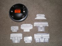
I like the idea of the woofer sitting over the top of the compression driver in a coax paraline. The BMS 4540ND is a natural choice due to its small size. It would be interesting to see what the newer B&C Speakers DE7 and DE5 compression drivers could do on a paraline. I have not found anyone selling them in the U.S. yet. Parts Express said they could custom order them. Before I get into that, I need to finish my current paraline project.
One of the things I've done to help visualize the driver layout for the paraline is print out true to size images of the drivers. This really helps determine if your driver placement will work in real life.
One of the things I've done to help visualize the driver layout for the paraline is print out true to size images of the drivers. This really helps determine if your driver placement will work in real life.
Attachments
JLH,
Hard to understand why you can't find B&C drivers here in the U.S. Perhaps because they are being rebadged under other names and there is some agreement not to sell them directly here as a B&C driver. The BMS drivers are interesting looking from the information I have seen but I have no direct experience with those drivers. I guess JBL decided they could make a few changes and produce their own version cheaper, they always seem to do that in the end. They remind me of Apple, they will steal an idea and then say they invented the idea.
Steven
- Home
- Loudspeakers
- Multi-Way
- Square Pegs