Hi Cviller of course you are right. But we assumed that everything else were ok.
Then the estimation should be easier, if one understands the circuit in detail.
I have an extra set of Power FETs, but the way I assembled the amp, makes it a little difficult to change them. So I would prefer to avoid it.
But I will measure the resistor, start the amp with a bulb device, and post the results.
Once I did read the complete F5 building threat, but I dont remember if anyone ever published a schematic with measured voltages ?
Best regards
Arthur.
6L6,
Thanks for posting so many detailed pictures.
I'm not sure where the location for the audio star ground should be.
Looking at the photos of the F5, it seems the location for the star ground is on the electrolytic cap board.
This makes sense, because it allows a short ground wire from the electrolytic caps to the binding post.
But it would also mean a low current audio ground wire would need to go to the amp.
However, I've read its an audio star ground - so the star ground location should be on the amplifier board.
However, that would mean dragging a large gauge ground wire from the electrolytic caps to the amplifier board first
and then it would go off to the binding post.
The theory of the star ground location being on the amplifier board makes sense - in theory.
However, practically - a short wire from the electrolytic caps to the binding post seems better.
Please advise.
Also, as AndrewT has informed me, on the power switch, both the hot and neutral should be switched.
This is protection in case the hot and neutral are mixed up coming out of wall socket.
.
Attachments
Looking at the photos of the F5, it seems the location for the star ground is on the electrolytic cap board.
This makes sense, because it allows a short ground wire from the electrolytic caps to the binding post.
But it would also mean a low current audio ground wire would need to go to the amp.
Yes, all the above is correct.
However, I've read its an audio star ground - so the star ground location should be on the amplifier board.
The way you say it, that makes sense. And it's very logical.
But remember, an amplifier is just an AC oscillator for the DC power supply. The neutral position of the speakers is audio GND, which is the center of the PSU board.
However, that would mean dragging a large gauge ground wire from the electrolytic caps to the amplifier board first and then it would go off to the binding post.
Which then wouldn't really be a starground - as the speaker Black would be connected to a different place than the amplifier board's GND...
(The speaker would be connected to the amp board, not the PSU GND, but the amp board would be connected to GND...)
That is not the most clear explination, it's late...
GND is not actually zero, it's just the center of the PSU's voltage potential. Reference everything back to that "center", and it will work properly.
There are only 5 wires connected to the output of the PSU GND;
L speaker black
R speaker black
L amp board GND
R amp board GND
Chassis (through the CL-60 as a ground-lop breaker)
The theory of the star ground location being on the amplifier board makes sense - in theory.
It also works quite well in practice. (no sarcasm intended, it might read that way)
However, practically - a short wire from the electrolytic caps to the binding post seems better.
This is where I am confused... because the amplifier is wired that way...

The last bit of information to remember about the wiring is that the input RCA jacks should be isolated (floating) from the chassis, and the input should have a discrete wire for + and - per channel. Don't connect the input to the chassis or PSU.
Hopefully some of this will help.
Also, as AndrewT has informed me, on the power switch, both the hot and neutral should be switched. This is protection in case the hot and neutral are mixed up coming out of wall socket.
If it's legal in Canada to do that (it is in the US, but not in some European countries) then by all means do so. I didn't only because my switch was a SPST.
P.S. - The photo in your post actually dosen't show the entirity of the GND wiring -- But this one does;
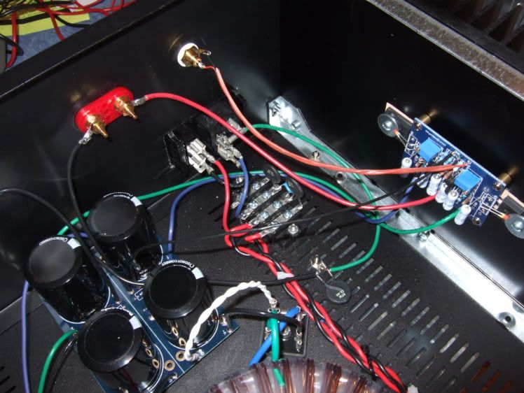
You can see the Black wires to the binding posts, the black wire to the CL-60 then to the Chassis, and the thinner black wires from the amp board to GND.
Last edited:
Do not ever locate the Audio Ground on the PSU link between the smoothing Caps. Never ever !!!!
Locate the Audio Ground in mid air somewhere near the amplifier and near the Speaker terminals and near the input RCAs.
Bring a 3wire triplet (+G-) from the PSU to the amplifier.
Locate the Audio Ground in mid air somewhere near the amplifier and near the Speaker terminals and near the input RCAs.
Bring a 3wire triplet (+G-) from the PSU to the amplifier.
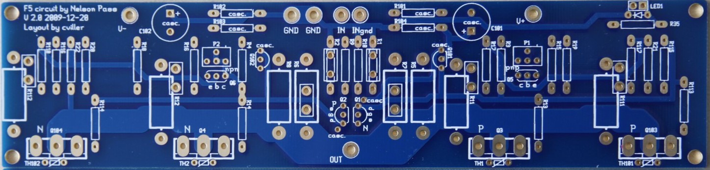
Do you mean as on cvillers pcb's Andrew where all grounds are connected with a single ground wire going to the p/s centre.
http://www.diyaudio.com/forums/blog...390-gb-f5-guide-pcb-version-2-f5_v2_front.jpg
http://www.diyaudio.com/forums/blog...390-gb-f5-guide-pcb-version-2-f5_v2_front.jpg
hi,
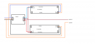
Would this diagram help you out? I know it different but it does show where all wires do connect,
the first one is for UKToecutter's turbo boards,external output boards.. but there is a typo there.
Last edited:
6L6 and NoSmoking
thanks for posting your photos - they are very helpful.
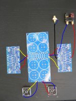
NoSmoking - On your amp, +Ve/Gnd/-Ve go to the amplifier board first
The Audio star ground node seems to be where the 3 blue wires meet (RCA shield - power supply Gnd in - speaker Gnd out)
Then from the amp board, the speaker Gnd goes off to the binding post.
So the star Gnd is on the amp board.
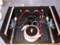
6L6 - on your F5, the speaker Gnd wire goes straight from the power supply board to the speaker binding post.
I think this puts the star Gnd node on the Power supply Cap board.
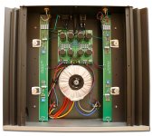
Here is a photo of Mr. Pass's F5.
Tricky to tell - but it looks like the audio star ground node is near the RCA jacks.
Also, to point out - After looking at photos of 6 different power amps - the +Ve/Gnd/-Ve DC supply lines,
going from the power supply caps to the amp, are heavily twisted.
and kept well away from any AC or rectifier ines.
.
thanks for posting your photos - they are very helpful.
NoSmoking - On your amp, +Ve/Gnd/-Ve go to the amplifier board first
The Audio star ground node seems to be where the 3 blue wires meet (RCA shield - power supply Gnd in - speaker Gnd out)
Then from the amp board, the speaker Gnd goes off to the binding post.
So the star Gnd is on the amp board.
6L6 - on your F5, the speaker Gnd wire goes straight from the power supply board to the speaker binding post.
I think this puts the star Gnd node on the Power supply Cap board.
Here is a photo of Mr. Pass's F5.
Tricky to tell - but it looks like the audio star ground node is near the RCA jacks.
Also, to point out - After looking at photos of 6 different power amps - the +Ve/Gnd/-Ve DC supply lines,
going from the power supply caps to the amp, are heavily twisted.
and kept well away from any AC or rectifier ines.
.
Attachments
Last edited:
Hmmm...
Is this 'wrong' ??
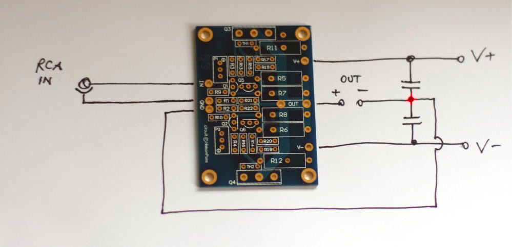
I dont think so, that's Peter Daniels illustration from his thread isnt it? I wired mine like this and it is dead silent.
Russellc
That's exactily what I'm getting at... I've done 2 this way, and with different boards, and it works fine.
I'm still quite curious about the way AndrewT describes, and will try it, as soon as he diagrams the specifics.
I'm in the middle of a build, I'll be watching!
Russellc
Hmmm...
Is this 'wrong' ??
I don't know - I was hoping you guys could tell me.
It seems that the high current loops are short - which is good.
But maybe the length of speaker cable needs to be taken into consideration.
In RF circuits, as the star ground potential moves up and down
all the stages connected to that node move up and down together.
However, in audio circuits it seems that star grounding is performed to stop
the creation of current loops which could create 60Hz hum.
It seems that when a L and R channel are placed in the same case,
a loop can be formed by the L and R interconnects, the amp and CD player.
So maybe both the L and R channel need to be taken into consideration when thinking about star grounding.
It seems most amps I've looked at, are wired like NoSmoking has shown.
.
- Home
- Amplifiers
- Pass Labs
- An illustrated guide to building an F5