I posted to the main F5 thread regarding a power supply problem and never received an answer. I have a few wrinkles in my design which I will try to describe. I have quite a few old SK147 and J72 Toshiba fets, the good ones, which bias beautifully at 5ma with 10 ohm source resisters. They are limited to 15volts so I cascode them using another similar fet biased with an LM329DZ which is rated at 6.9 volts. I note Nelson recommended cascoding if necessary. This did not seem like a problem to me. I wanted to use the power supply from Zen3 ( the one with the zener regulator) which I have used before with no problems as I have 24 volt toroids putting out around 35 volts. The output side is stock. Finally my problem is this: using the regulator my positive side pins to only 4 volts and no current flows and the negative is correct at around 24 volts and a small current flows. The cascodes are not biased properly on the positive side clearly and the bias is not correct. If I connect the power supply directly to the B+ and B- and by-pass the regulator everything is fine and I can set up the bias without difficulty and no offset issues. For completeness I do not use a printed circuit and use the frogy style with my fets and resistors glued to a ground plane copper board. I presume there is some sort of oscillation going on and my scope is limited in range so I cannot see it. Has anyone else seen this or can someone point me to a forum where this has been discussed.
Tom
Tom
Try to post a schematics of you modded setup (AMP and PSU) and write in the voltages you have measured. Based on your describtion, your problem could be anything from an error in your cascoding to a bad soldering. I don't think you have oscillation, because that tend to show up as burned components, but you never know...
Thanks for the reply. I do not have a software to draw schematics however mine is basically stock except for the cascode. This is basically another SK147 or SJ72 with the source connected to the drain of the main input fet, the drain is connected to the resisters as normal and the gate has the LM329DZ from ground and loaded with a 17K resistor to the regulated +. I have not added the current limiters yet and haven't hard-wired the circuit to the PS using 20 inch hookup wires with alligator clips, the output mosfets are mounted on the heat sinks. The circuit for the regulator is exactly as in Zen variations #3 and I am using 330uF caps on both the zener chain ( a 15 volt and a 13 volt in series )and the output. I have tried increasing the current through the zeners by dropping the resister from 1500 to 750 with no change. If I disconnect the .47 source resisters from both sides, the input fets bias perfectly at around 50mv and the regulators are both around 24 volts. I think I will try the other version where you use a 47.5K resistor from the PS and omit the zener chain and see how that works. I merely wanted to get rid of the ac spikes and drop some volts.
I have quite a few old SK147 and J72 Toshiba fets. They are limited to 15volts
Maybe I read it other than you intended, but the K147 handles 40V and the J72 does 25V, just as the 400mW and 200mW afterbirths.
I was looking at datasheets again and you are quite correct. I remember Erno Borbely years ago when he published his pre-amp in Audio Amateur stating not to use them higher than a drain of 15 volts and this stuck with me. On re-reading that old article I noticed that the recommendation was for low noise in his phono stage and he cascoded also to reduce the effect of the rather large input capacitance as well. I'll remove the cascodes and see if it makes a difference. I doubt noise would be an issue in an amplifier of this type. I am pretty sure my heat sinks can stand a 30volt rail.
The SJ74 can handle operationally, i.e. in RMS much higher than 25V. Note that when the swing is 20V (peak) up, the gates are high too (10/60 * 25 = 4V, but that does not harm the jfet at all in 90% of F5 implementations that have a rail of 22V.
But the cascode has a different effect: reduces the gate current, gives a second harmonic structure to the input.
Tip: I would rather put the tail on the source of the jfets, or have it float in a similar way. Why I would place the tail of the cascode bias different than to earth: the 8V peak-peak is still seen by the drains. A fixed voltage cascode in the manner of the F5-C gives the jfets a very hard time!
I used a 20K/5k resistor pair for the bias. I have that in my Zen I/V implementation (to a good effect). A transistor might sound better than a cascode of two jfets. (that is also too expensive imho)
albert
But the cascode has a different effect: reduces the gate current, gives a second harmonic structure to the input./QUOTE]
I don't understand what you mean by reducing the gate current. Dr. Hawkesford wrote some interesting papers about using cascodes both for the input side and also the output side and showed significant reductions in distortion. Again that was with transistors and may not apply to fets.
I agree that setting the reference gate voltage for the cascode at the source is a more desirable way of doing this and also that the pass device is probably less important and could be a transistor, tube, etc but this gets away from the Fet concept. If you use a resistor divider do you not get a modulation of the signal at the gate of the cascode device whereas a device such as a LM329DZ or Lm336-5.0 volt would keep the source to drain voltage differential more constant which would benefit the gain device and I would guess keep it more linear. I am not an engineer so probably way over my head here.
I tried removing the cascodes and with the higher drain to gate voltages the current increased however the amp worked fine. Just had to drop the RL via the trimpots. When I tried to use the regulators there was no change with the + regulator fixed at 4 volts and the - at 24 volts. The plus side shut off and the negative side conducted a small amount upseting the feedback bias. My next step is to try the capacitance multiplier approach.
I must admit I find it fascinating how Mr Pass has allowed us to use devices with a very limited class A voltage range ( eg +/- 50mv for these types ) to deal with input signals of the order of several volts all in Class A. The implications for a line amp seem clear to me.
Hi, this is the background of what I mean:I don't understand what you mean by reducing the gate current.
see Le Monstre by Hiraga, 1983, in part 1. The schema shows that the configuration is similar to the F5, except the output pairs (Darlingnot) are now FETS in the F5 of a type not yet commercialized at that time imho.
Cascode input current reduction
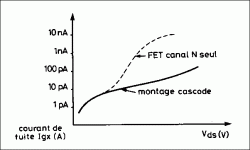
Getting a lower gate current improves the transparency. The gate current of a single 2SK170 will change a lot when the Vds changes - and in the F5 with the low feedback, Vds does change a lot.
cascode jfet/transistor distortion
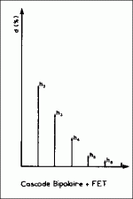
This is highly audiophile quality, good to have when applying feedback.
cascode jfet/jfet distortion
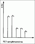
You see this is not a really 'audiophile' input combo. On feedback, higher order distortion starts to increase.
Of course the Miller effect vanishes too.
Hiraga also says that the combo of a biasing of the cascode with a zener sounds worse. (Now your "super"zener IC might sound better than a stock zener, but I just want to mention it anyway.)
Just my two pennies.
albert
Last edited:
These are the two types.

Andrew,
The jfet+cascode on the top is the winner. This nice harmonics goes for the earthed config.
So it works like this in the Zen I/V, but for the F5 the bottom of the bias circuit has to be connected to the source, sort of 'floating', as far as Hiraga's recommendations go.
albert

Andrew,
The jfet+cascode on the top is the winner. This nice harmonics goes for the earthed config.
So it works like this in the Zen I/V, but for the F5 the bottom of the bias circuit has to be connected to the source, sort of 'floating', as far as Hiraga's recommendations go.
albert
Of course the text should be "The jfet+bipolar transistor cascode on the top" [of the illustration].
for me a transistor is a bipolar NPN or PNP device; I would never call a jfet a transistor. Just my nomenclature.
This is the input of the described amplifier of Hiraga [without the feedback], just to see the overview of the input of that reference:
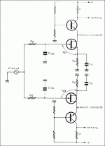
albert
for me
 a transistor is a bipolar NPN or PNP device; I would never call a jfet a transistor. Just my nomenclature.
This is the input of the described amplifier of Hiraga [without the feedback], just to see the overview of the input of that reference:

albert
Pass DIY Addict
Joined 2000
Paid Member
6L6 : I guess I'm a bit late to the party, but you have an EXCELLENT build and this is a GREAT thread! Thank you!
I also love the Musical Fidelity chassis re-do! I was wondering where those great sinks came from!
All of this makes me want to build an F5, but I'm not sure what I'd do with it once it was completed. I already have a trio of Aleph-X amps and an A40. I use the A40 in my office at work and just love it! I have contemplated building an F5 and a DCB1 into the same chassis for kicks...
Great work, all!
Eric
Last edited:
Then relabel the diagram jfet/bjt.....the text should be "The jfet+bipolar transistor
This way no one should be confused.
Then relabel the diagram jfet/bjt.
This way no one should be confused.
Done; thanks
triode_al
Do you have any data about the distortion when you bias the cascode from the source of the fet rather than ground as you mentioned earlier. If this voltage can move from +/-4 volts as you shown, biased at the source pin of the fet would keep the drain voltage at a fixed level presumably linearizing the gain. Perhaps some would remember how Borbely did it in his later all-fet line amp ( AudioXpress, May 2002 ) with K246 and J103 cascoding the K170 and J74 using self-bias. I don't know how that sounded as I never built that amp. I could never get his dual differential designs to equal a good triode stage.
Do you have any data about the distortion when you bias the cascode from the source of the fet rather than ground as you mentioned earlier. If this voltage can move from +/-4 volts as you shown, biased at the source pin of the fet would keep the drain voltage at a fixed level presumably linearizing the gain. Perhaps some would remember how Borbely did it in his later all-fet line amp ( AudioXpress, May 2002 ) with K246 and J103 cascoding the K170 and J74 using self-bias. I don't know how that sounded as I never built that amp. I could never get his dual differential designs to equal a good triode stage.
triode_al
Do you have any data about the distortion when you bias the cascode from the source of the fet rather than ground as you mentioned earlier. If this voltage can move from +/-4 volts as you shown, biased at the source pin of the fet would keep the drain voltage at a fixed level presumably linearizing the gain.
Perhaps some would remember how Borbely did it in his later all-fet line amp ( AudioXpress, May 2002 ) with K246 and J103 cascoding the K170 and J74 using self-bias. I don't know how that sounded as I never built that amp. I could never get his dual differential designs to equal a good triode stage.
tpark, This is getting quite off track probably.
- sorry I only have the degradation curves shown earlier and not with a floating Vsource of 8 V pp. Would be interesting. However, it does not work to measure with a closed loop (a running amp). But looking at the curves we see the bad effect of the floating source:
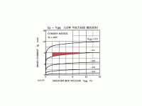
The jfet is 'forced to bump around'.
Well of course we keep 15-20 dB away from the worst case situation, so in practice . . . we are all happy anyway; and some like the ensuing distortion when driven hard.
I remember Borelby connecting the sources together, so Vds of the bottom unit stays constant.
albert
I am sorry to have started this topic and I realize the cascode thing was off-topic but we can always learn something. On rechecking my wiring I found I had the diode on the plus side in backwards and therefore fortunately for me this blocked the zener chain and basically shut off the pass device therefore the 4 volts. My bad. The channel is cooking as I type this and seems stable. I have however gone to attaching the base of my reference zener to the source of the bottom fet and will see how it sounds when I finish the amp.
- Home
- Amplifiers
- Pass Labs
- An illustrated guide to building an F5