Probably?
That's why I'm waiting for clarification.")
I respect Andrew, but it is bold talk to say Daniels is "very" wrong...explainations I would like to see and impliment.
Russellc
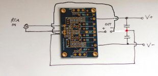
I dont think so, that's Peter Daniels illustration from his thread isnt it? I wired mine like this and it is dead silent.
Russellc
I have my earth separately from the input sockets go to the star ground, which I have in the middle of the caps rail the caps rail. I have one earth line for both channels.
Just my way of trying to be precise.
I agree completely.
But as I said, I will happily try out Andrew's scheme, I am very curious!
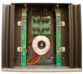
Again - its tricky to see - but it looks like an Mr. Pass's First Watt F5 is wired is almost like AndrewT has described.
NoSmoking's picture shows it beautifully.
If you carefully look at Mr. Pass's First Watt F5 - you'll see a green wire coming off the power supply cap board
going toward the RCA jack.
Bet you the star ground point, is on the amp board, somewhere near the RCA jack.
Actually, it looks like there are 3 posts on the amp board, near the RCA jack.
6L6, if your F5 is working fine, would it be best to leave it as it is ?
.
Last edited:
Clarification.
If you look carefully at Mr. Pass's First Watt F5 - on the amp board, right near the RCA jacks,
There are 4 wires that come up underneath the board, and are soldered from the top.
1 of those wires is the input.
However, the other 3 are soldered to the same track.
They would be - power supply Gnd, RCA Gnd & Gnd going to the speaker binding post.
So the star Gnd node, is on the amp board, near the RCA Jack.
Attachments
Clarification.
If you look carefully at Mr. Pass's First Watt F5 - on the amp board, right near the RCA jacks,
There are 4 wires that come up underneath the board, and are soldered from the top.
1 of those wires is the input.
However, the other 3 are soldered to the same track.
They would be - power supply Gnd, RCA Gnd & Gnd going to the speaker binding post.
So the star Gnd node, is on the amp board, near the RCA Jack.
I have done it exact this way by my F5 clone.
Star ground at the amp boards 1 wire to the PSU works very well, dead silent
I respect Andrew, but it is bold talk to say Daniels is "very" wrong...explainations I would like to see and impliment.
Russellc
^ Ditto!
- John
the science behind it makes sense. As I understand it, its because there are high transient currents passing through the power supply cap junction star point, it is better to reference it to a quieter star. this can also be done by T'ing off the star connection between the caps and bringing out a connection from there to connect to, so the signal return currents are passing through a point connected to power ground, rather than the PSU star connection itself.
both will work obviously, because they are still referenced to the same voltage, but its cleaner to have the star at the amp boards, which are then connected to the power supply star through a single connection, like papa is doing.
both will work obviously, because they are still referenced to the same voltage, but its cleaner to have the star at the amp boards, which are then connected to the power supply star through a single connection, like papa is doing.
Clarification.
If you look carefully at Mr. Pass's First Watt F5 - on the amp board, right near the RCA jacks,
There are 4 wires that come up underneath the board, and are soldered from the top.
1 of those wires is the input.
However, the other 3 are soldered to the same track.
They would be - power supply Gnd, RCA Gnd & Gnd going to the speaker binding post.
So the node, is on the amp board, near the RCA Jack.
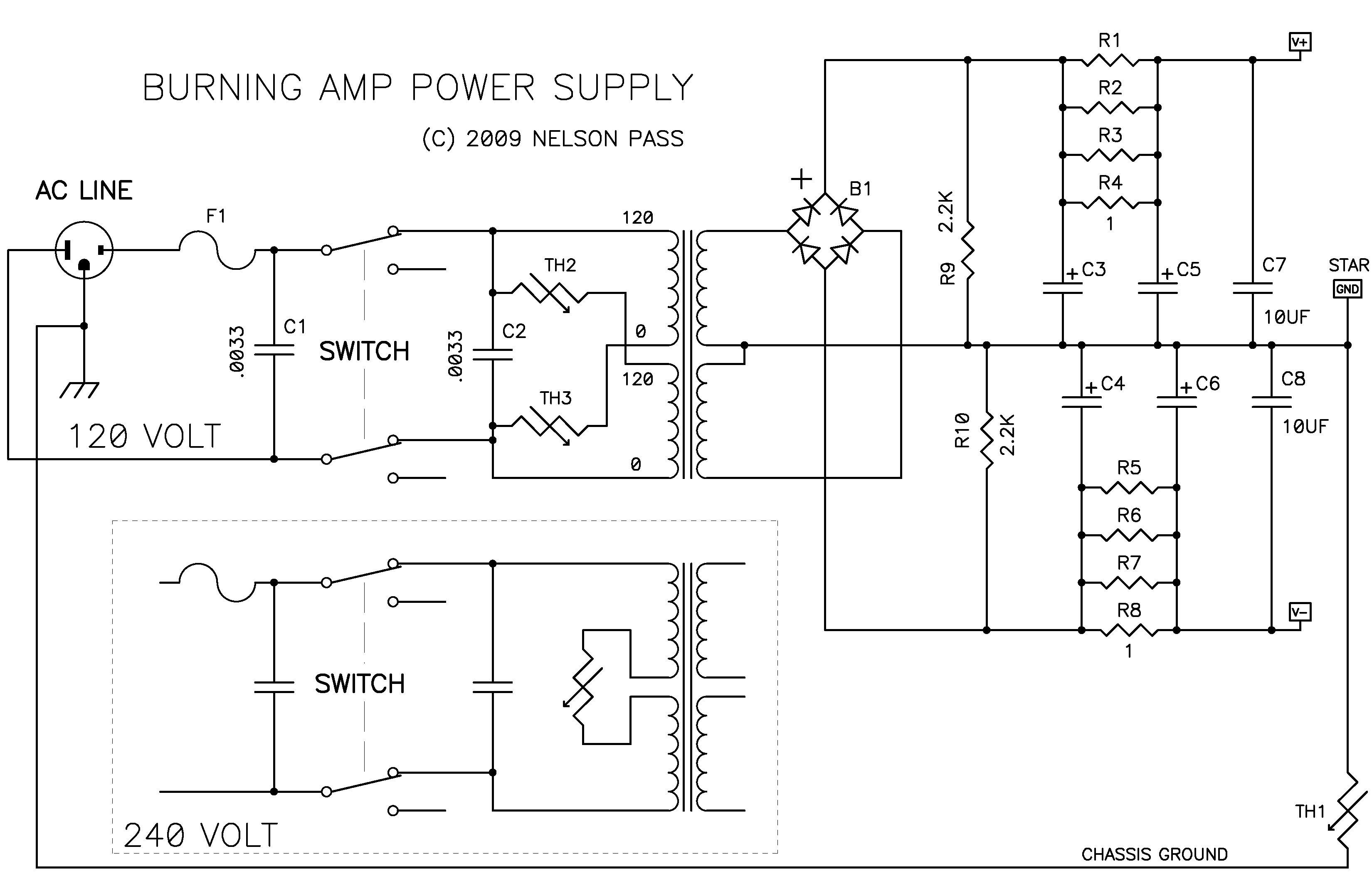
Star Gnd is on power supply! Check also :
why does that prove the star is on power supply? that to me can just as easily suggest that this point is connected TO star ground, just as is being suggested
If you have stereo, and hence two PCB's - then each will have its own local substar, any way you interpret this schema.
But I suggest to have the ground of the inputs to the 'central star' , else the tangible and non-neglectable voltage differences between the two boards will also run though the earth.
Ohms law: 2 amp over 0,01 ohm = 20 mV. This 20 mV can disturb the input line signal.
sure, i'm not saying one discards power supply star, just that it may be best to have the signal returned to a point that has less extreme charging currents flowing directly through it. I tend to have a star for each of the sections and then join them at a central location. most of my current builds are using ground planes so its a little different. the amp i'm building at the moment is 6 channel (2 x 'the wire' LPUHP, 2 x 'the wire' lateral fet+lme49830 nand a pair of class D in the same case) plus some battery powered logic and monitoring, as well as sequenced power (beaglebone)
Last edited:
post392.
The audio ground or star ground is NOT on the PSU.
Note the link between the PSU zero volts and the star ground.
This is the same link that post389 refers to. It is the same link I have referred to.
It is universal advice.
Except for those that insist on doing it wrong and locating the Audio Ground between the smoothing caps.
It seems that when a L and R channel are placed in the same case,
a loop can be formed by the L and R interconnects, the amp and CD player.
So maybe both the L and R channel need to be taken into consideration when thinking about star grounding.
.
This is my position too: earthing both input cinches to [widely] separate parts [PCB's on both sides] in the amplifier will easily give rise to disturbances from peripherals. That is why I prefer one earth from the inputs.
my

Yes, that earthing at the input is a suggested solution of both Self & Leach.This is my position too: earthing both input cinches to [widely] separate parts [PCB's on both sides] in the amplifier will easily give rise to disturbances from peripherals. That is why I prefer one earth from the inputs.
my
Yes, that earthing at the input is a suggested solution of both Self & Leach.
Please enlighten me on Self & Leach
- Home
- Amplifiers
- Pass Labs
- An illustrated guide to building an F5