Not so sure Big VA is always so desirable...charging will be short and steep...I have a feeling the over voltage will be better. Like running the amp at 60 V and only allowing 50V swing. (or what ever the numbers might be) then it would be possible to have some voltage over the signal level at all time regardless of the current output, like an effective way of separating the voltage from the current.
their claim for the high price?
I agree that the bridged LM4702 type output stage is amusing, for that much cash.
(likely that stuff wouldn't sell as well at half the price)
The lower bound on C is a function of Vdc, so as in theory that can go as high as you like then C can go as low as you like. You have a multi-variable optimisation problem, so there is not a one-dimensional answer. You need another constraint, such as Vdc no more than 10% above the minimum possible - which roughly corresponds to 10% droop.gootee said:Not looking for optimum C, yet. Just simply bounding C, and really only the lower bound.
I think this is an useful thread (apart from the 'noises off'), but your searches via simulation may need to be better informed by 'ideal model' algebra as that will guide you to the tradeoffs which a simulation can sometimes obscure.
Of course, having found constraints on C you still need to take account of other issues such transformer heating, PSU efficiency, feed inductance etc. as you have said.
DF96,
I would be very happy if we can arrive at some rule of thumb that has at least been tested theoretically and maybe confirmed practically. At the moment most of us are not even guessing close to anything useful. I can almost assure you that you have often also not paid enough attention to your power supply design as it is almost always secondary. Here we talk only amplifier schematics, second and 3rd order harmonic level. Triple EF current mirror.... Never power supply.
No disrespect to any of our members starting a thread believing that they are offering the best sounding amplifier ever. Just look at the SIMS slew rates of several thousand volts per uS, a bandwidth ranging from DC to Daylight and very low H2 with H3...... Totally forgetting to discuss the accompanying power supply with equal enthusiasm. But power supplies are boring, it is a transformer normally salvage from some other equipment and capacitors, enough to arc-weld with, bypassed by some little cap for HF luck plus a resistor that will discharge it over a fortnight.
Unless everything is equal no-one that builds this amp could for the love of god have the same results even if they all agree that it simulates perfectly.
Last edited:
... how much droop you can stand, which is essentially the same as ripple: droop = ripple pk-pk (roughly). How much droop you can stand depends on how far above peak signal voltage you started from, among other things.
...
So 5C = 0.02/C so C = sqrt (0.004) = 63 246 uF, and then E = 0.63 P.
...
DF96
Thats a pretty interesting take, I've never seen this issue presented this way.
Thanks for taking the time.
Can you give a copy of that posting?
"So yes the early effect may or may not be significant (equivalent to some -60db) but it sure is helpful to review the impact."
I roughly calculate -70db but rounded down.
Hope this helps
-Antonio
Nico, this link has already been referred to many times on diyAudio but it may be worth having it stated here again as part of the thread, as something people can also refer to, as an all-in recipe for getting some figures: Elliott Sound Products - Linear Power Supply DesignI would be very happy if we can arrive at some rule of thumb that has at least been tested theoretically and maybe confirmed practically. At the moment most of us are not even guessing close to anything useful. I can almost assure you that you have often also not paid enough attention to your power supply design as it is almost always secondary. Here we talk only amplifier schematics, second and 3rd order harmonic level. Triple EF current mirror.... Never power supply.
Frank
Steven @ #713:
EE- & EI-core have small air gaps - the laminations dont quite meet up, and are insulated. Even a very small air gap (10's of um) has a significant (beneficial) effect on the saturation performance - it "tilts" the BH curve, reducing B (lfux density) for a given H (MMF).
Toroidal (tape-wound) cores do not have an air gap, they are wound from a single strip (unless they are "cut-cores", which have been sliced in half, etched & lapped & glued back together - specifically to create a small air gap).This means that the toroidal cores saturate sooner, and more abruptly, than EE/EI cores.
A secondary (har har) effect is the coupling. line-frequency EE/EI cores are usually wound with a split bobbin - primary on one half, secondary on the other with a big divider in between. This is great for electrical safety (isolation/hipot/safety regs) but absolutely terrible for magnetic coupling - the windings dont occupy the same volume. This results in high leakage inductance (which turns into poor regulation).
Toroids inherently have better coupling as one winding encloses the other. You could wind a toroid so this doesnt happen, eg primary on one half of the toroid, secondary on the other - but your xfmr manufacturer will probably stab you with a pencil if you suggest it (I've seen it done at HF in SMPS & RF gear, to minimise capacitive coupling).
This means the toroidal transformer has lower leakage inductance than EE/EI transformers. And the leakage inductance (plus the resistance, but leakage usually dominates) is all that limits the short-circuit = inrush current.
So toroids saturate harder and faster than EE/EI cores, and suck more current when they do. So what, you might ask?
I suspect this means the toroid will be designed with a peak flux density that is somewhat lower than the saturation flux density Bsat, to prevent saturation at peak line voltage cos its so nasty. It'll still saturate at turn-on, hence soft-starting (and even if it didnt, the DC bus caps need soft-charging).
Whereas EE/EI transformer designers exploit the small air gap, and push the peak flux density very close to saturation. this allows them to reduce core material and/or turns, saving money and weight.
The resulting saturation is what creates the nasty peaks in the no-load current waveform. My guess is that manufacturers of decent audio mains transformers DONT do this, but I might be wrong.
If we use a "T" model with primary and secondary resistances & leakage inductances (Rp, Rs, LLp, LLs) along with the primary magnetising inductance Lm, we see that the magnetising current flows through the Rp & LLp, then down thru Lm - it does not flow through the secondary.
The secondary current flows thru Rs & LLs, then is reflected to the primary and flows thru Rp & LLp (but not thru Lm).
So when the transformer saturates, Lm drops rapidly, so the magnetising current rises rapidly, Im => Im_sat. This extra mag current drops even more volts across Rp & LLp, which reduces the voltage across Lm. And that voltage is what the transformer reflects to the secondary: Vsec = [Vin - (Imag + Isec*Ns/Np)*(Rp + jwLLp) ]*Ns/Np
[Microwave Oven Transformers actually exploit this - under no-load (Isec=0) the core fully saturates each half-cycle. But under load the Isec*(Ns/Np)*(Rp + jwLLp) volt drop reduces Vmag enough to prevent saturation. Its a sneaky trick, and means if you test an MOT with no load it will look like its faulty - I measured a 230V MOT drawing 6Arms no-load!]
Conclusions:
If your power transformer does not saturate (no-load current looks pretty sinusoidal) and the magnetising current is small (say < 10% of rated current) then you can ignore the Imag*(Rp + jwLLp) voltage drop. This means you can reflect Rp and LLp to the secondary and lump them in with Rs & LLs. This is a very simple model, comprising Ns/Np, Rs' and LLs' (which include the reflected Rp & LLp)
Conversely if your power transformer does saturate, and/or the magnetising current is large, the Imag volt-drop term is important, and you need to use the full "T" model.
Anyone got a bunch of different power transformers for audio amps lying around and can test this? all you need to do is look at Ip with no load......
Some links to papers with equations for linear power supply circuits:
http://www.google.com/url?sa=t&rct=...4oGAAQ&usg=AFQjCNHmxBxGmiBPOesMW1jkDQb5cKrqDw
http://techpreservation.dyndns.org/beitman/abpr/newfiles/Rectifier Analysis Part 1.pdf
http://cbasso.pagesperso-orange.fr/Downloads/Papers/bulk capacitor calculations.pdf
http://www.google.com/url?sa=t&rct=...4oGAAQ&usg=AFQjCNHmxBxGmiBPOesMW1jkDQb5cKrqDw
http://techpreservation.dyndns.org/beitman/abpr/newfiles/Rectifier Analysis Part 1.pdf
http://cbasso.pagesperso-orange.fr/Downloads/Papers/bulk capacitor calculations.pdf
Last edited:
Frank/Tom, thanks for the links it should be good for refreshing the memory and rid some of the cob-webs. However, I think that your simulations has been far more revealing in what effect it has on what we hear than purely the equations available.
I remain thankful for what you guys have done thus far it has been quite an experience to bring the theoretical and practical together in a simulation.
Although I do not have an absolute answer yet, I but have a very good foundation and make some practical measurements using a practical amplifier by comparing the input signal to the output signal while changing reservoir capacitor values. This comparison is very simply performed comparing the input- with the NFB signal.
My first task is do an exemplary and totally blameless amplifier lay-out and a simple system by which power supply parameters can be adjusted and signals recorded consistently.
Last edited:
Hi,
I know that I can not help the solution with transformer capacitors. I abandoned this path, certainly for reasons of work and I should refresh my memory on all formulas around the transformer. also know the limits, even using a high-flux toroidal transformer with good capacitors.
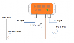
just out of curiosity, I want to show that with electronically, you can get good performances. but even in this way, we want new circuits, new philosophies, like the one I show. (not happy about the cost,then not in production, have 10 proto only).
is based on an intelligent controller. The output voltage is not stabilized compared to the input (as transformers).
This devices has a fixed ratio (Vout = (Vin-12%) and can operate from 30V up to 200V input.
short cut protection without shunt.
includes soft start.
BW is 20Mhz
One important (also for other psu/smps circuit) is reset time , need for perfetct balanced voltage while successive transient current running.
this is all.
I know that I can not help the solution with transformer capacitors. I abandoned this path, certainly for reasons of work and I should refresh my memory on all formulas around the transformer. also know the limits, even using a high-flux toroidal transformer with good capacitors.
just out of curiosity, I want to show that with electronically, you can get good performances. but even in this way, we want new circuits, new philosophies, like the one I show. (not happy about the cost,then not in production, have 10 proto only).
is based on an intelligent controller. The output voltage is not stabilized compared to the input (as transformers).
This devices has a fixed ratio (Vout = (Vin-12%) and can operate from 30V up to 200V input.
short cut protection without shunt.
includes soft start.
BW is 20Mhz
One important (also for other psu/smps circuit) is reset time , need for perfetct balanced voltage while successive transient current running.
this is all.
Attachments
Last edited:
Yes, that's the fun thing. I've been attempting to design 4-quadrant lab PSU for own use but didn't get much beyond the initial concept.
It's basically a bridged symmetrical power amp with a transient response ranging into several MHz. It would use software controlled U/I actuators driving the 'amps'. Audio amp technique at HF, with a high tolerance for various loads required, both capacitive, inductive and ofcourse resistive. The lab supply will not know what master pieces you'd connect") It took too much effort, in such way that it would be a whole project on its own, away from the main effort, realizing my intended amp design. That's a long time ago though, I just bought a lab supply and was done with it
It took too much effort, in such way that it would be a whole project on its own, away from the main effort, realizing my intended amp design. That's a long time ago though, I just bought a lab supply and was done with it
It's basically a bridged symmetrical power amp with a transient response ranging into several MHz. It would use software controlled U/I actuators driving the 'amps'. Audio amp technique at HF, with a high tolerance for various loads required, both capacitive, inductive and ofcourse resistive. The lab supply will not know what master pieces you'd connect
It took too much effort, in such way that it would be a whole project on its own, away from the main effort, realizing my intended amp design. That's a long time ago though, I just bought a lab supply and was done with it Tony,
I am working on it.
Here is a sample of some of the data I have generated with the simulations I mentioned earlier.
I am also working on using square waves, for testing. So the results in the examples might change.
Cheers,
Tom
Hi Tom,
Maybe you could have discussed the importance of this data
Originally Posted by gootee
Tony,
I am working on it.
Here is a sample of some of the data I have generated with the simulations I mentioned earlier.
I am also working on using square waves, for testing. So the results in the examples might change.
Cheers,
Tom
Hi Tom,
Maybe you could have discussed the importance of this data
What a coincidence. I just came back to post the rest of it.
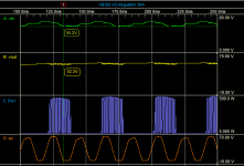
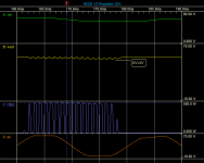
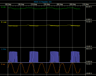
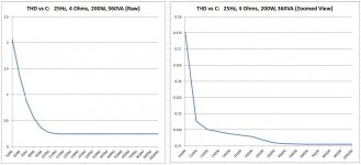
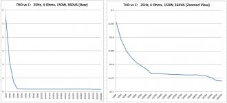
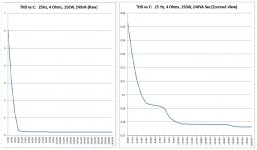
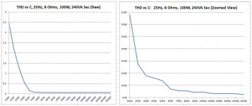
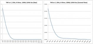
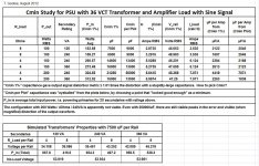
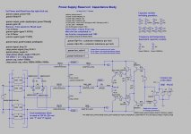
Below are the schematic used for the simulations, the main table of initial results, some info about the power supply behavior (because if that's no good then the data might be no good), plots of THD vs reservoir capacitance, and a zip file with the simulation files plus the Excel spreadsheet that has all of the data in it.
Please understand that I used THD here only as a tool (with an incomplete amplifier), only in order to more-easily find the minimum viable capacitance value, during C-value sweeps, to find the point (C value) where the PSU itself was no longer deforming the amplifier's output waveform due to the capacitance being too low. Otherwise, I would have had to try to very-closely inspect the output error plot and the signal output plot. And then there also would have been no real context for the swept capacitance values.
After all of that, I still didn't know exactly how to actually CHOOSE the minimum capacitance, from the data. So I tried a couple of ways:
First, I looked at the THD for a huge capacitance, then backed up until I found a THD that was 1.01 times the THD with the huge capacitance. The capacitance value found that way in labeled "Cmin 1%", in the table.
Second, I just "eyeballed" the plots and tried to pick a minimum value that was past the more-vertical section of the plot, without being too greedy about the THD, which was not changing much anyway, and while trying not to think about the uF per Amp that would result. That process was very difficult to be objective about, especially after expanding the low-level portion of each plot. The minimum capacitance found that way is labeled "Cmin from Plot", in the table, and might be more or less meaningless.
Note, too, that the plots posted as jpgs are not "to scale". The horizontal axes just have all of the data points, in sorted order. I also did some plots with linear scaling. They're in the Excel spradsheet file, in the zip file attachment, along with the actual raw data tables.
The transformer model was fed with about 144% higher voltage than I used when measuring the real transformer for the model, i.e. 173 VRMS instead of 120 VRMS. That way, it has an output level that's more like a 36 VCT transformer's secondary. Maybe I should note that when I originally tested it, I did so with both the primaries and secondaries paralleled, because a) that's how I was using it, and b) the modeling algorithm I had was only for single-primary/secondary transformers. I'm hoping that since it was in that high-current configuration when I measured it, and it was also designed for use with 230 V mains, that maybe the model won't be too far off. Anyway, I posted a little table of transfomer data that I took from the simulation, hoping that one of the transformer experts here will either pronounce it DOA or give a review of its good and bad points. (I will try to make whatever data is needed, for that, with the simulator. The original physical measurements are posted in this thread, in the transformer model schematic, or I can provide them again if that's too difficult to find.)
Oh, in order to be able to sweep the capacitance automatically, I used some equations that I found in a paper somewhere to calculate the ESR and EPR on the fly. ESR = {0.02/(cap_value*Vrating)} and EPR = {1/(0.01*cap_value)}. I used Vrating = 100 Volts. ESL was just set to 10nH.
Now that I have the setup built, it wouldn't be TOO terribly difficult to do it over again, if model changes are needed.
Cheers,
Tom
Attachments
-
 4Ohms_360VA_200W.jpg47.5 KB · Views: 69
 -
 4Ohms_360VA_150W.jpg48 KB · Views: 72
 -
 4Ohms_240VA_150W.jpg54.5 KB · Views: 78
 -
 8Ohms_240VA_100W.jpg47 KB · Views: 86
 -
 8Ohms_120VA_100W.jpg48.2 KB · Views: 101
 -
 Data_Tables.jpg145.3 KB · Views: 110
 -
 PSU_Test_Schematic_tpg.jpg114.7 KB · Views: 211
 -
PSUTest20AUG.zip155.7 KB · Views: 49
Last edited:
- Status
- This old topic is closed. If you want to reopen this topic, contact a moderator using the "Report Post" button.
- Home
- Amplifiers
- Power Supplies
- Power Supply Resevoir Size