Yes, although Ed Simon said he had to fix a lot of his mistakes, Whitlock had electricians pull out hot and neutral from conduit and twist them together, to reduce the differential fields induced in the safety ground. I suspect that would have quite an effect on our inductance "estimates".
It will reduce the inductance from about 225 nH per foot to about 180 nH per foot. It will also depend a bit on how they twisted the pair. If they used a drill, chances are it relaxed a bit and opened the spacing, but if they did small lengths by hand preventing the twist of the individual wire, it will not spring back as much. Absolute number between 180 and 200 nH per foot will depend on how it was twisted. Honestly though, they are looking for integrated magfiend cancellation, not lowering of inductance.
Yes, I have. For a ten foot length of twisted #10, #12, and #24, I measured values within 4% of the Terman equation. Not bad considering the low level of inductance. It does require zeroing the meter properly though, as setup inductance can skew the results at these low levels.Anyone tried measuring, what a concept?
Not bad considering the small numbers. I remember speaker cables can run the range of 10 nH per foot all the way to about 350nH depending on the design.I've measured speaker cables - they have similar conductor spacing to mains wiring and they run around 1uH/m round trip inductance as a ball-park.
Actually, a cylindrical conductor has 15 nH per foot internal to the conductor, but you are correct otherwise.Just to further mix this up I grabbed a 50' extension cable and measured it (shorted at the far end) at 100 Hz, 1KHz and 100 KHz and for all three I got 3.5 uH.
I think you got bit by meter lead cal. Did you zero out with a short first?
Remember a wire in space has no inductance. Its only in a circuit that it has inductance. And the closer the two conductors are the lower the inductance.
At least make them drive a Buick.
I didn't realize you could be so cruel.
jn
Not bad considering the small numbers. I remember speaker cables can run the range of 10 nH per foot all the way to about 350nH depending on the design.
What did the design of the 10nH/ft one look like - you've eliminated some of the internal inductance of a cylindrical conductor at that extremity?
I too can’t see how the magnetic storage can supply a sustained need for energy. I am thinking only of (brief) transients.
Agreed. Getting any reasonable amount of energy stored inductively is a real problem.. IR losses are constantly there unless you go super. Then, it's a case of structural containment, as the field and forces get very large very fast. Copper yields in compression when the storage device gets in the 20 tesla range. That's why they use Hastalloy now as a HTS backer.
The kick can be pretty bad..LHC found that out, we have a coupla 6 tesla mags which store about 1.5 megajoules, they will kick big time..At one of the shows, Gray was demonstrating it's ability to store massive amounts of energy by energizing it with a ***DC*** current, then flipping a switch which shorted a lightbulb across it, the flyback voltage causing the lightbulb to flash.
se
Yes.
V= L*dI/dt is the mechanism by which the choke will function by counteracting any sudden change across it. The emf has a negative sign.
Ref. L nonlinearity: I should have been more clear : The L of the choke is a function of the permeability mu of the “iron”. Close to saturation, mu drops very low, thus L drops low , same with emf too. End result, miniscule reaction.
At frequency, one needs the full model. Ls/Rs, where Rs is the sum of resistive losses in the wire as well as eddy lossed in the steel.
jn
What did the design of the 10nH/ft one look like - you've eliminated some of the internal inductance of a cylindrical conductor at that extremity?
Me personally, I used a braid over braid coax. It is also possible to do so with ribbons, as the width of the ribbon increases the path reluctance. (my avatar is the field profile of a braid over braid coax.). But the conductors must be against each other to reduce external inductance and increase capacitance.
Within a pure cylinder like a solid wire, the internal magnetic field (DC) linearly increases to the wire surface. If you remove internal material from the conduction, you lose some storage so the internal inductance goes down. This is exactly what happens with skin effect. A cylindrical shell has no internal magnetic field.
I use a simple rule of thumb for a shell or braid for internal inductance..divide 15 nH by the aspect ratio of the braid...thickness divided by circumference, or even simpler, the number of wires in the braid.
jn
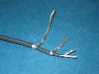
ps. It looked like this. Here, I made a triple braid, but was counting on the two outer for the speaker connector, the inner braid is actually the shield for the core wire, I was using that coax for feedback from the speaker.
Attachments
Last edited:
Thank you, SY, for your input. Now what does Scott think?
I'd connect it as a follower and ground the plus input, output floating.
When are you lot over there going to start using Napoleonic units for distance?jneutron said:NANOHENRIES PER FOOT
Incidentally, the idea that only a loop can have external inductance was one which I only grasped relatively recently (a few years ago). Maybe I slept through that EM lecture 40 years ago. Or maybe I did know but then forgot. When you buy a 10mH choke, what you are actually buying is a device which will add about 10mH to a closed circuit if you substitute it for a piece of wire (provided it has little or no magnetic coupling to the rest of the circuit). The choke itself has no (external) inductance, because it does not form a loop. Slight caveat: stray capacitance might 'complete' the loop for an unconnected choke, but then you are not measuring the choke but 'choke +capacitance'.
When are you lot over there going to start using Napoleonic units for distance?
When they can afford it.
For JC
Maxim AN1957
TI sloa067 section 4.2.1
Cheers
Stein
Attachments
When are you lot over there going to start using Napoleonic units for distance?
Sigh..probably never in my case...I am indeed an old dog..
When I give talks or tours, I constantly mix mils, inches, microns, nanometers, feet, meters, kilograms, pascals, psi, farenheight, centigrade and kelvin.
I've tried..but can never get the hang of it..
But in my defense, thermal resistance in electronics is typically Degrees C per inch...

jn
JNeutron-
I rechecked my measurement. ESI Videobridge 2150, did the short and open cal. Checked with a standard inductor and got the appropriate value. Checked the short and got 50 nH. 50' of extension cable (not sure of the internal construction) and got 3.2 uH. All at 1 KHz.
I'll dig through my stuff to see if I can find a 3 uH inductor to cross check. The standard was much larger. That may take a while.
The small stuff --
 This reminds me of a project i coordinated.... how much inductance does a 200 tonne ying-yang magnet have - built with superconducting metal and bathed in a continuous flow of liquid Helium? I was the electrical power coordinator for ($300M) all the power -from designers to building contractors -(ac/dc/pulsed) for the project using 2 such magnets in a containment vessel to trap and contain and squeeze the fields to creat a suspended plasma at super high temps. Talk about emi/rfi and diagnostic issues? on a grand scale. The shielding walls were 12 feet thick super dense lead/concrete mix. A good place to cut your teeth for audio. Zzzzz -RNM
This reminds me of a project i coordinated.... how much inductance does a 200 tonne ying-yang magnet have - built with superconducting metal and bathed in a continuous flow of liquid Helium? I was the electrical power coordinator for ($300M) all the power -from designers to building contractors -(ac/dc/pulsed) for the project using 2 such magnets in a containment vessel to trap and contain and squeeze the fields to creat a suspended plasma at super high temps. Talk about emi/rfi and diagnostic issues? on a grand scale. The shielding walls were 12 feet thick super dense lead/concrete mix. A good place to cut your teeth for audio. Zzzzz -RNM
Last edited:
I may not have made that clear. Bill's motivation was to balance the coupling into the safety ground, not reduce hot-neutral inductance.It will reduce the inductance from about 225 nH per foot to about 180 nH per foot. It will also depend a bit on how they twisted the pair. If they used a drill, chances are it relaxed a bit and opened the spacing, but if they did small lengths by hand preventing the twist of the individual wire, it will not spring back as much. Absolute number between 180 and 200 nH per foot will depend on how it was twisted. Honestly though, they are looking for integrated magfiend cancellation, not lowering of inductance.
jn
Brad
Rough estimate coming up:1audio said:50' of extension cable (not sure of the internal construction) and got 3.2 uH. All at 1 KHz.
Assuming RF characteristic impedance of 100 ohms, and velocity factor of 0.8 due to insulation, then I get an inductance of 417nH/m ( =100/(0.8*c) ), so 50' (15.2m) will be 6.3uH at low frequencies. I did say 'rough estimate'! So this cable seems to have a lower RF characteristic impedance, more like 50-60 ohms.
At 1kHz this will have a reactance of 0.04ohms which could be smaller than its resistance. This cable will not look at all like 50-60 ohms characteristic impedance at 1kHz.
Rough estimate coming up:
Assuming RF characteristic impedance of 100 ohms, and velocity factor of 0.8 due to insulation, then I get an inductance of 417nH/m ( =100/(0.8*c) ), so 50' (15.2m) will be 6.3uH at low frequencies. I did say 'rough estimate'! So this cable seems to have a lower RF characteristic impedance, more like 50-60 ohms.
At 1kHz this will have a reactance of 0.04ohms which could be smaller than its resistance. This cable will not look at all like 50-60 ohms characteristic impedance at 1kHz.
Most wire pairs off the shelf are going to have an effective dielectric constant between 3 and about 6 or 8. While the plastics run an epsilon of roughly 3, the inductance spillage outside the cable confines raises it.
V =1/sqr(EDC), so velocity will run from .57 to .35, about 30 to 60% lightspeed.
Granted, some exotic cables use foamed dielectric with epsilons in the 1.05 to 1.5 range, but not line cords.
I don't think it's good to assume an extension cord has the same impedance that a piece of romex does (here in the USA at least). However, your calc'd numbers are more consistent with what I'd expect of an extension cord..
I do wonder about the conductor geometry however, as 3.5uH is kinda low for 50 feet, 63 nH per foot is what I'd expect of very low voltage (thin insulation) 4 conductor wired star quad.
Demian, thank you for the time and effort in testing the cable..
John
View attachment 293830 This reminds me of a project i coordinated.... how much inductance does a 200 tonne ying-yang magnet have - built with superconducting metal and bathed in a continuous flow of liquid Helium? I was the electrical power coordinator for ($300M) all the power -from designers to building contractors -(ac/dc/pulsed) for the project using 2 such magnets in a containment vessel to trap and contain and squeeze the fields to creat a suspended plasma at super high temps. Talk about emi/rfi and diagnostic issues? on a grand scale. The shielding walls were 12 feet thick super dense lead/concrete mix. A good place to cut your teeth for audio. Zzzzz -RNM
I googled ying yang magnet...what I really wanna know is...was that "biped" in the picture....you in a Klatu suit??
ITER is also a cool one..
jn
Darn, I missed a shot also...
Sigh..
Actually, my estimation was right, except it's second part, when I multiplied inductance by 4 assuming I connected both wires in series, in the same direction, like I did a day before with winding of transformer in order to get 60 Henry choke for a filter.
When actually of course they go in opposite direction, so the closer they are, the lower will be resulting inductance. Speaking of straight wire VS loop, straight wire actually have theoretically inductance, but in order to measure it you need a loop. I don't want to start Schrodinger Cat's talk here, but if you can't measure inductance that does not mean it does not exist.
How does "inductance spillage" raise effective permittivity? We are talking about a twin wire, enclosed in a dielectric? I would expect the effective permittivity to be a little less than the actual insulation because the insulation is relatively thin and surrounded by air. Are you referring to coupling between adjacent turns in a coil of cable still on the drum?jneutron said:Most wire pairs off the shelf are going to have an effective dielectric constant between 3 and about 6 or 8. While the plastics run an epsilon of roughly 3, the inductance spillage outside the cable confines raises it.
I thought that there is an ambiguity in how you define the surface area for calculating flux linkage, so with no loop it can be argued that inductance is undefined. However, I have never used an isolated inductor so real life still works OK!Wavebourn said:straight wire actually have theoretically inductance
I've lost why anyone cares to know what L of a simple wire/conductor is -- but lets say we want to do some measurments that might relate to emi/rfi or even filtering on the ac line to prevent entering the audio amps: A place to start would be giving everyone the following info -->
The ac cord (or wiring) is a transmission line at RF and is a lossy transmission line. At low freqs, AC network analysis applies. As the freq increases, the Z decreases because of the parallel C between wires. Further increases in freq, there is a transistion band where the series L starts to take affect and the decreasing input Z asymptotically meets the constant characteristic Z.
For an ac cord or wiring the transition band is between around 100KHz and 1 MHz.
-RNMarsh
By Z do you mean characteristic impedance? I would have put the transition band a little lower in frequency, but it does depend on the details of the cable construction. It is a pity that mains wiring is not more lossy at RF as that would decrease interference and discourage mains-based signalling.
- Status
- Not open for further replies.
- Home
- Member Areas
- The Lounge
- John Curl's Blowtorch preamplifier part II