For people who have not written papers on DA in caps like Richard Marsh and I have, many here sure think themselves 'experts' on DA, its effects, etc.
People often think of 'distortion' as ONLY 'non-linear distortion'. There is a 'linear distortion' as well, and DA represents it best. Now is there a 'non-linear' component in real DA? Of course there is, but it is secondary. ANY real process is non-linear to some degree, and people often confuse the MODEL of DA with the actual working mechanism of DA. DA is molecules, 'dancing to the music' and in turn absorbing and holding a certain amount of input signal, only to release it later, either as signal or heat.
DA shows a DIFFERENCE OF PATH of the signal passing through the capacitor, compared to the ideal or calculated path of the signal passing through a virtually 'perfect' capacitor. IF the paths of a nearly ideal cap and an ordinary cap were virtually identical, there would be NO DA.
All caps distort somewhat. It just depends how deep you look. However, most ceramics and tantalum caps have MORE non-linear distortion than most other caps. This was known and published 34 years ago. Most capacitors have DA, much more than non-linear distortion, but the generation of non-linear distortion is below the threshold of most audio distortion measurement equipment. So, you can have a DA of 3-10%, yet measure almost no non-linear distortion, with most distortion measurement equipment.
This is the dilemma. Just because DA is not defined as an essentially non-linear mechanism, can we ignore it?
Well, IF you are inclined to limiting yourself to sinewave testing, perhaps so. That is one good reason why we can use Mylar caps at the input of our test equipment, and not notice any problem. However, if you test with asymmetric pulses, you will find plenty of deviation from the ideal or predicted path. Now is this important? I think yes, because music is NOT just a sine wave or two, but has dynamic asymmetrical components, just look at music on an oscilloscope or measure for the asymmetry, and there are papers showing this asymmetry in program material. Interestingly enough the typical BBC announcers voice is a prime source.
Now, do you want to ignore something that is continually changing the path from what would be predicted by typical Spice simulation, or mathematical analysis. That I have to leave to each and every designer. For me, I just don't use high DA caps in my equipment. Works for me! '-)
Fair enough, I was leaving the door open so that if there was a corellation it would certainly deserve to be explored. Still stumped on the rectfying terminations cancelling perfectly for sine waves.
I know the horse is dying, but I must point out bringing up the mysterious rectification in the first plase was an insinuation that there was real harmonic distortion with pulse waveforms and not sinewaves. Which remains an extraordinary claim.
That is not the connection I wanted you to think. I was talking about sim's and models not being complete but simplified..... such as two h2 out of pahse would simplify to 'what ever caused it' to be dropped.
It was speculation on my part that perhaps a couple contacts or ?? could do this - you find the model for it - This spculation comes from details of resistor end cap terminations which cause distortion and is -in fact- used to determine QA/QC issues in mfring and is tested for by H3.
The resistor end caps are often a poor conductor (brass or steel) known itself to be of some small measureable issue (Not saying it is heard... I dont go there). Note the Dale have no end caps and measure better as well as being more reliable.
The termination inside the cap is usually Very poor compared to R's. And corrosion and oxidation abounds over time. Especially for electrolytics/bipolars. The effect is more of an issue for high current apps flowing thru these internal connections. Is it audible under any use... I dont go there but seems it could. I hope this helps clear up the comment or perspective....and better connects the dots. Pulse waveforms show other "potential" issues and are not contact/weak diode related. --RNM
Last edited:
There was an insinuation that the "other" effects scale with DA so it was a sufficient indicator, this is clearly not so.
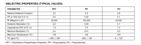
Has anyone here ever checked whether the "other" effects scale with DF (tan /\) instead of DA?
I always liked this parameter (DF) better when judging capacitor performance from the data sheets, to be honest.
Attachments
To put it another way: feeding a current into a cap and measuring the voltage vs. applying a voltage and measuring the current, will give different results for higher order distortions. This is the same algebra as re-entrant distortion from feedback loops.
Voltage/current way of thinking over capacitors as above, brings to my mind the below quote that I
read in Heaviside Electromagnetic Theory Vol. I, Ch.II, para 77, pages 93-95
(Not related to distortion but equally difficult to grasp)
For a condenser connected to a suitable source, so as the transverse voltage between the plates is held constant, the stored energy will increase with the increase in capacitance through the use of higher permitivity insulator between the plates.
But when the charges are constant (when plates are insulated), the use of the higher permitivity insulator between the plates, will reduce the stored energy of the condenser
This has puzzled me as I think of that:
1. In a transformer-rectifier- capacitor PSU: Is the capacitor in the two states above, vis. constant voltage when rectifier is conducting and constant charge when rectifier is off?
Or
2. The case of a capacitor kept charged through a constant voltage source and alternatively through a constant current source
George
Who are these 'experts'? Certainly not me; I am just a humble physicist/engineer. Fortunately it is not necessary to be an 'expert' to find gaping holes in some of the claims made on here. The papers you refer to use sound theoretical and practical techniques, are peer-reviewed and appeared in reputable journals?john curl said:For people who have not written papers on DA in caps like Richard Marsh and I have, many here sure think themselves 'experts' on DA, its effects, etc.
Of course, as DA is linear!!So, you can have a DA of 3-10%, yet measure almost no non-linear distortion, with most distortion measurement equipment.
What do you mean by "path"? DA occurs within the dielectric, in exactly the same place as the signal '"path".IF the paths of a nearly ideal cap and an ordinary cap were virtually identical,
Deviation from ideal cap with no DA, or ideal cap with DA modelled by a CR ladder?However, if you test with asymmetric pulses, you will find plenty of deviation from the ideal or predicted path.
The effect of inserting or removing a dielectric is quite different from charging or not in a PSU. Essentially, the mechanical work involved in moving the dielectric changes the electrical energy stored in the cap so energy conservation is still true.gpapag said:This has puzzled me
Just because DA is not defined as an essentially non-linear mechanism, can we ignore it?
Well, IF you are inclined to limiting yourself to sinewave testing, perhaps so. That is one good reason why we can use Mylar caps at the input of our test equipment, and not notice any problem. However, if you test with asymmetric pulses, you will find plenty of deviation from the ideal or predicted path. Now is this important? I think yes, because music is NOT just a sine wave or two, but has dynamic asymmetrical components, just look at music on an oscilloscope or measure for the asymmetry, and there are papers showing this asymmetry in program material. Interestingly enough the typical BBC announcers voice is a prime source.
Sorry John this is contradictory, any test waveform can be decomposed into sine wave components. If what you say is true (DA is essentialy linear) superposition is violated. I told you a few posts ago what fools some folks into making their conclusions, the difference between a single sinewave in two different R/C networks is a tiny amplitude and phase shift or a small signal that for all intents and purposes looks just like the input.
Scott, now you will be accused of playing Fourier games!
If someone can show me a piece of music which cannot be put on repeat play (periodic) or includes discontinuities (infinite in number and/or size) then I will accept that Fourier theory cannot be applied to all music. Even then, it can still be applied to all other music.
If someone can show me a piece of music which cannot be put on repeat play (periodic) or includes discontinuities (infinite in number and/or size) then I will accept that Fourier theory cannot be applied to all music. Even then, it can still be applied to all other music.
Strictly speaking Q=CV may only be true for a constant capacitance, but it is nearly true for real capacitors which are approximately constant.
As a capacitor charges up it can change capacitance, whether through mechanical movement or changes in the dielectric permittivity. Both of these changes are likely to be symmetric with respect to voltage, so if +10V causes a 0.5% increase in C then -10V will also cause a 0.5% increase.
If a positive signal peak is treated in the same way as a negative signal peak (i.e. the capacitor has a symmetric or even response to voltage) then the signal will suffer odd-order distortion. The order of signal distortion will be one greater than the order of capacitor non-linearity. (The same rule applies for resistors: a linear (e.g. first-order) resistance change with voltage would cause second-order distortion to the signal.)
Permittivity vs. electric field. The curve is usually symmetric about zero electric field, and typically rises with electric field.
DF96
Thank you for clarifying.
Now I am able to understand what you are talking about. You are talking of distortion caused by
change of capacitor’s capacitance (when fed with an AC signal)
1. Due to dimensional changes - e.g. distance of plates- with the signal
2. Due to changes of the dielectric permitivity with the signal
Dimentional changes as I read can be induced by electrostriction and piezoelectricity (properties of the dielectric) as well as Coulomb-electrostatic-forces acting between the plates. Electrostriction is met on all dielectrics. Piezoelectricity on some ceramics.
For the dielectric permitivity changes with the signal, I suspected that you imply some form of hysteresis mechanism existing in a capacitor.
I made a search and I found that indeed there is a relevant property named ferroelectricity. This, together with pyroelectricity are met on some ceramic dielectrics.
These properties are powerful enough to be utilized for producing ceramic actuators, digital memories, SAW wave filters, temperature sensors.
But for capacitors, all these have the potential to become heavy sins. Are they really?
Crystalline silicon (centro-symmetric) is not piezoelectric or ferroelectric. I don’t know what is the case when it is doped. Scott, help
George
Reducing MLCCs' piezoelectric effects and audible noise
http://ecadigitallibrary.com/pdf/CARTS06/4_1kln.pdf
Electrostriction - Wikipedia, the free encyclopedia
Ferroelectricity - Wikipedia, the free encyclopedia
Flexoelectricity - Wikipedia, the free encyclopedia
http://material.eng.usm.my/stafhome/sabar/EBB443/Chapter%205-Ferroelectric%20Ceramics.ppt
http://www.imit.kth.se/info/SSD/KMF/2B1750/2B1750_06_Ferroelectric%20Ceramics.ppt
Last edited:
The effect of inserting or removing a dielectric is quite different from charging or not in a PSU. Essentially, the mechanical work involved in moving the dielectric changes the electrical energy stored in the cap so energy conservation is still true.
Well, maybe I read it wrong. But I doubt that Heaviside was meaning the case of moving the two different dielectrics in and out of the plates.
George
Edit:Heaviside gives the energy of the capacitor equal to ½ *S*V^2
Where S=permitivity of the dielectric, meaning in modern terms the capacitance, V=Potential (Voltage)
Last edited:
Everyone, what is differential subtraction? Think what it is, in reality. It is the subtraction of two separate RC time constants, where the ONLY variable is the variation in the test capacitor when passing a specific test waveform, compared to a more ideal capacitor. The RC time constants are adjusted as close as possible, and this can be done to 0.001% without much problem, by using similar caps, especially of very high quality. Then, the capacitor under test is substituted, and EVERY effort is made to get the same result. This includes careful adjustment of the RC difference, reduction in rise-time of the test waveform to remove any inductive differences, adding series R in the BETTER cap to match low frequency ESR differences, etc. Just do this with every cap you can find to test. Then, you might realize that better caps, match better to best caps commercially available, and some caps deviate amazingly so. However, you MUST use an asymmetrical waveform to get clear results. That brings out the differences. Apparently, symmetrical AC is self canceling for all practical purposes and little is seen.
Now before jumping on me for the test waveform, think about using a bandwidth limited Square-wave as a test signal for distortion. Do you see the problem? The harmonics generated by the device under test will essentially rest on top of the test waveform and it is almost impossible to cancel the original square-wave well enough to see the original. That does NOT happen with a sine wave, or even 2 sine waves, if they are unrelated, so we can easily test with these test signals.
Would you still insist on using a square-wave for harmonic or IM distortion tests?
It is the same with DA. In this case, the DA components are equally charged and discharged within a cycle and nothing much happens, UNLESS you increase the test frequency so high that the charging and discharging actually causes losses that shows itself as DF or dissipation factor. In fact, at RF frequencies some crappy audio caps might explode from overheating. It seems an indication of something not being right.
'-)
I'd use mylar.I am out of this topic. Going to write papers on DA. Is plain printer paper Ok, or I should use something special?
I'd use mylar.
How would you write on mylar? It is very slippery.
3. Ionization of solutions1. Due to dimensional changes - e.g. distance of plates- with the signal
2. Due to changes of the dielectric permitivity with the signal
4. Change of molecular structure
And wasn't he a stand-in for Marky Mark? Oh wait, wrong forum.Google is your friend : How to Mark Mylar | eHow.com
- Status
- Not open for further replies.
- Home
- Member Areas
- The Lounge
- John Curl's Blowtorch preamplifier part II