Excellent scheme!Wow that should take care of the drive problem! I am eager to see your measurements when it is done!
Congratulations, you can make a quality transformer phase shifter, the project will be the top in the HI-END.
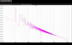
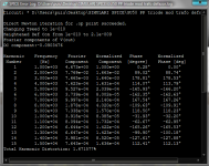
We made a simulation in LTC, but because I had a tube 6SR7 model, we used a small 6N8S changes.
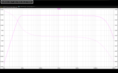
Simulation results are very good in the power of 15W and inductance using the proposed scheme recommended by the author.
The results you see here:
Attachments
Excellent scheme!
Congratulations, you can make a quality transformer phase shifter, the project will be the top in the HI-END.
We made a simulation in LTC, but because I had a tube 6SR7 model, we used a small 6N8S changes.
Simulation results are very good in the power of 15W and inductance using the proposed scheme recommended by the author.
The results you see here:
Actually this a very comparable schematic (and one of my favorites), some 15 years or so ago (Sound Practices):

@LAZAROIU: in your triode strapped schematics, you use ECC85.Would there be a Russian equivalent that could be use in place of them? I have plenty of Soviet double triodes but no ECC85.....
Why not ECC81 (12AT7)?
--
No matter the quality of capacitors?But I personally like 3 last schematics more than both Sergeev's schematics: coupling capacitors from drivers to grids of output tubes is evil.
No matter the quality of capacitors?
Grid currents are non-linear, so any capacitors will be charged by rectified signal shifting bias, modulating signal by it's own envelope.
Hey,
Have corrected a few errors and used Koren and Bench´s models that are reliable.
You will have to work with the working points as it´s not up to your specs.
The concertina must have higher Ua to work properly, it now is in the ballpark of 50V.
I am not fully aware of how the SRPPs with 27k on top works? Also they seem to run on very low current, 1,5mA.
The GU50 ran on ca 40mA but should maybe run ca 100mA/tube, A knows.
The transformer inductances where much off. Use 2.5H for the primaries and .08H for the secondary to get 4k/8. Gives you a low 40H primary but that´s good enough for initial sims. If you go for 5.55H, secondary should be 0.18H. 5.55/0.048 is ca 15k/8. But maybe strange things happen when you go with cathode windings?
Also some Spice-commandos should be adjusted.
Would it be possible to see the schematics with the corrections that you made?
Regards,
François
Grid currents are non-linear, so any capacitors will be charged by rectified signal shifting bias, modulating signal by it's own envelope.
Hmm, never thought of that... In that case, driving the interstage transformer with an EL34 with RC coupling does not look that good.
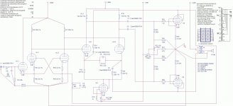
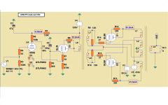
Left:
0.5v sensitivity
50(70) W output
25-35000 Hz bandwidth (-1 dB)
THD (10W) 0.05%
S/N ratio: 92 dB
Speed: 45V uS
Right: transformer details
Right bottom: used tubes
Hi,
Can you explain what the first triode (VL1.1) do? No anode resistor? No cathode resistor?
Hi,
Can you explain what the first triode (VL1.1) do? No anode resistor? No cathode resistor?
R6
Grid currents are non-linear, so any capacitors will be charged by rectified signal shifting bias, modulating signal by it's own envelope.
This is of great interest to me.
How can I check for this non-linearity? 100X scope across the grid resistor maybe?
This is of great interest to me.
How can I check for this non-linearity? 100X scope across the grid resistor maybe?
It is dynamic in nature. You can check it by measuring filtered DC, by R-C networks with higher R value than grid leak resistors, applying different levels of signals.
It is dynamic in nature. You can check it by measuring filtered DC, by R-C networks with higher R value than grid leak resistors, applying different levels of signals.
OK got it!
OPT Question
Some questions on the OPT. Also, could you please recommend an alternative source or method using off-the-shelf transformer, Amplimo's version is way too expensive!
Thanks,
Jaz
Some questions on the OPT. Also, could you please recommend an alternative source or method using off-the-shelf transformer, Amplimo's version is way too expensive!
Thanks,
Jaz
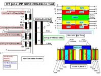
With pleasure, have in the schematic drawing data for OT GU50 PP (triode mode), Raa = 3700ohmi (4000ohmi)
There are two variants: with core E + I-section of 18 cm * 2 and another on the core C-core section of 8-10cm * 2.
The coil design is the location but also their connection phase.
For a PP pentode will be recalculated for Raa = 5000ohmi.
I hope the drawing is understood.
If there are questions, answer with pleasure.
The transformer is made practical and works in multiple copies, project schematics and the OT is personal.
Excuse my English!
Last edited:
Some questions on the **********************
Thanks,
Jaz
*****************************************************
I apologize for mistakes slipped in drawing was not intentional.
We corrected diagram. Please contact me if something is not clear.
Output transformer is made very easy and the results are very good.
Thank you for your interest per sis to be useful.
Attachments
*****************************************************
I apologize for mistakes slipped in drawing was not intentional.
We corrected diagram. Please contact me if something is not clear.
Output transformer is made very easy and the results are very good.
Thank you for your interest per sis to be useful.
Thank you! What are the recommended core material used, either EI or C?
Jaz
Thank you! What are the recommended core material used, either EI or C?
Jaz
Hello!
I do not know which is your location, but for me it was easier to find cores C-core Russian TV, very good cores, TC-40 TC-90, or TC-180...... So I recommend C-section core with at least 8 cm * 2.
But doing well and E + I with a minimum core section of 16cm * 2.
- Status
- This old topic is closed. If you want to reopen this topic, contact a moderator using the "Report Post" button.
- Home
- Amplifiers
- Tubes / Valves
- PP GU50 triode strapped project