Connect both Main Audio Grounds of a stereo amplifier to chassis. This is what helps stop you killing some toddler (child) who sucks the end of an interconnect.
With the Signal Ground of both amps inside the stereo amplifier connected to their respective Main Audio Grounds and with both connected to chassis, when you connect a stereo interconnect to the input you will find hum on the stereo amplifier output/s.
The only way I have found to attenuate the output hum of a stereo amplifier is to decouple the Signal ground of both channels from the power/mains audio ground.
With a monoblock or with a dangerous stereo amplifier with floating Main Audio Grounds, you will find that the hum is already attenuated.
I have connected the chassis to mains ground. Will try the new ground scheme in my new amp.
@Aguila. The lm3886 will work fine with 22-0-22 to 24-0-24V AC secondaries which will produce appx 32-0-32V DC to 36-0-36V DC after rectification and filtering. This is for use with 8 ohm speakers. VA ratings of 160 to 300 will be fine.
If your speakers are 4 ohm then ac secondaries should be between 18-0-18 to 20-0-20 AC secondaries.
Last edited:
Here is picture of the XY amp.
And my other projects
Audiodoc?s Photos
An externally hosted image should be here but it was not working when we last tested it.
And my other projects
Audiodoc?s Photos
Avbuilder:
Thank you for your information. I tried to order the Panasonic caps from the place you provided, but the shipping charge was way too high because they only have them in Europe, so I ended up ordering Wima's 2.2uF MKS type 63V they had available locally, they have 10mm pitch.
Your amp looks really nice, very neat. I checked the rest of your pictures and they all look very well made, congratulations!!! I will be using them as reference when I'm ready to put mine in a enclosure.
AndrewT/Pacificblue:
What happens if the Input GND is not cut and separated from Power GND in these boards?. I ask because there are two builders here that didn't go through the hassle of cutting them, and they have no hum in any of their amplifiers.
Question number 2: I see there is an equation to calculate the resistor value for the Mute pin in National's datasheet. I think that nobody here is using a switch in that mute pin connection, just the resistor. Should I calculate the exact value of that resistor, or the 10K Ohm or 22K Ohm I've been using are OK?.
Very nice work av. I liked your photo gallery too. Your wiring and enclosure layout is very good looking (and I'm presuming good sounding too!). May I ask what brand enclosure you're using for those two large amps shown on your table? They look very nice indeed.Here is picture of the XY amp.
An externally hosted image should be here but it was not working when we last tested it.
And my other projects
Audiodoc?s Photos
The are 8audio ones from hongkong and measure appx 30 x 8 x 20 cm. Here is a link:
Results for Case, Feet & Knob:Chassis & Casing
The small ones are from a seller along on ebay appx 25 x 18 x 5 cm. The former cost about 80 dollars and have been used by linuxguru for his my ref. I have made the EHHA headphone amplifier and gainclone in those (though I will replace the gain clone with a naim amplifier as soon as i get good heatsinks). The three later ones house a pass B1, quad Wolfson 8740 DAC and Mauropenasa MyRef Rev E.
UPDATE!!!
Yesterday, I decided to remove the Ci "feedback capacitor" or C4 in the XY PCB's of the new amplifiers I built recently. The reason behind it was that even though I used better quality components in these, I didn't like the sound they produced, it was too bright, the treble was too intense and the bass was kind of flat. In these new amps, I changed the value of Ri or R4 in the XY PCB's from 1K Ohm to 680 Ohm. I used initially the same type and value capacitor in Ci (C4) as I used in the first amplifiers, Elna Silmic II 47uF 50V.
This has been discussed in previous posts here in this thread, anyhow, I removed the 47uF and replaced it with a Nichicon Fine Gold 100uF 50V, so all the caps are the same in the new amps, C1, C2, C3 and C4.
This change has made a HUGE difference in the quality of sound, now the new amps sound great, the bass is more deep and robust, the highs remained the same but since the bass is deeper, more pronounced now, they don't feel as bright as before. It is incredible the difference this has made. Thank you, AndrewT once again...
After trying the three combinations, 1K + 47uF, 680 Ohm + 47uF and the last, 680 Ohm + 100uF for Ri Ci, I think that all of you guys using the 1K + 22uF combination that comes with the kit ARE NOT getting the best possible sound from your amplifiers, you all should replace at least the C4 cap.
For the "Pemo boards", I'll be using 680 Ohm for Ri plus 220uF 50V for Ci, as recommended by AndrewT. I couldn't use the 220uF now because I just ordered them, they should be here in few days, all I had now was Nichicon Fine Gold 100uF, but they did it, these things sound now better than ever. Compared to the first ones I built, these sounded always louder, I guess because of the 680 Ohm, but now the sound is more detailed, basically better bass and better treble. I highly recommend upgrading at least the C4, but the ideal would be to replace both, R4 and C4, using 680 Ohm for resistance, and at least 100uF for capacitance.
did you read post361? and post187?What happens if the Input GND is not cut and separated from Power GND in these boards?............
Last edited:
These cap value are not absolute............ I highly recommend upgrading at least the C4, but the ideal would be to replace both, R4 and C4, using 680 Ohm for resistance, and at least 100uF for capacitance.
They in conjunction with the resistor value determine the RC time constant.
That RC must be related to the input filter RC to ensure near zero AC voltage across the NFB capacitor.
Go back and re-read the formula. Post54. The RCs are linked to each other.
Last edited:
Here is the formula...!
C4 should be chosen so that in normal operation it has virtually zero DC voltage across it and virtually zero AC voltage across it.
Choose C4 value by using the equation
C4 >= C5 * Sqrt(2) * [R5+R6] / R4
The bigger you choose for C5, the bigger that C4 becomes.
Andrew, I read each and every one of your posts... Don't tempt me here to use the "P" word, please!
Anyhow, I never said the values were absolute, my point is precisely that, they are not, and they influence very much the quality of sound that comes off the speakers.
Now, the formula above includes C5, but I have not found any reference in National's datasheet about this cap affecting the sound, they only refer to "AC coupling at input and output for single supply operation". They only mention Ri and Ci as a low frequency pole (highpass roll-off) and Cf, Rf and Ri which are the "Zobel RC Network" as a high frequency pole (lowpass roll-off).
Based on this, I will be using a 2.2uF 63V MKS type capacitor for AC coupling, this is the only size I could finf that will fit the space on the Pemo PCB's. On the other hand, instead of 47uF or 100uF, I will be using 220uF in Ci and 680 Ohm in Ri as you suggested.
Is this allright, or the 2.2uF 63V MKS type cap will cause troubles?. I thought it was only for "AC coupling"...
The 2.2uF capacitor is the DC blocking capacitor as Andrew mentioned. This means that it prevents DC from entering the amp and destroying your speakers.
You can read about it on the My RefC thread where people have even bypassed it if the DC at output is very low or if your preamplifier already has a DC blocking output cap.
The higher the value of the input capacitor the lower the bass frequencies will cut off (high pass filter as told by Andrew). To explain in a simpler way with an arbitary example, say 1 mfd capacitor will pass frequency of over 40 Hz (so you lose the 20-40Hz band) while a 2.2 mfd one goes down to 20 Hz while a 10 mfd may gown down to 5Hz. Since healthy humans can hear from 20-20KHz, a 10 MFD will be an overkill (and enormous too). One can use from 1 microfarad and above however 2.2 to 4.7 will be the best.
After searching a lot of sites for a good yet small input cap I only found that the panasonic polypropylenes are the ones that fit.
The value of R3 feedback resistor determines the gain of the amplifier.
Polypropylenes are better than polyester ones. Try to find a 2.2 polypropylenes that fit. Wima MKP / FKPs are bigger however you may solder them from below. Here is my schematic and BOM:
An externally hosted image should be here but it was not working when we last tested it.
An externally hosted image should be here but it was not working when we last tested it.
An externally hosted image should be here but it was not working when we last tested it.
Last edited:
Continuing my research on lm3886 boards...
Hi again, this is PEMO.
Continuing my research on LM3886 boards, I also found this highly respected kit from BrianGT.
Here you can see part of one of his boards, where you can see that power ground and signal ground are.....tada.... connected.

NOTE: (Brian has the PDF document where I took this picture, protected. So if I am doing something wrong please let me know ASAP, to delete this message.)
3 out of 3. Why?
Best regards,
PEMO
Hi again, this is PEMO.
Continuing my research on LM3886 boards, I also found this highly respected kit from BrianGT.
Here you can see part of one of his boards, where you can see that power ground and signal ground are.....tada.... connected.
NOTE: (Brian has the PDF document where I took this picture, protected. So if I am doing something wrong please let me know ASAP, to delete this message.)
3 out of 3. Why?
Best regards,
PEMO
Your pic does show the connection.
Is the connection on the bottom side?
Hi Andrew, this is the only picture I found, I think this is the upper side of the board.
Why these three designers have grounds connected?
Why they sound so good?
Is this grounding issue just for safety or also to improve sound?
I really think that we can get something good out of this thread, at the end we will have a new board design, one that includes all the changes that have been discussed here.
Best regards,
PEMO
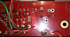
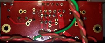
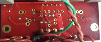
Here are some pictures of the bottom of the BryanGT amps. Hope they help
Edit: Long leads in pic #1 are just the excess from Uriah's Resistor Re-placer.
Edit: Long leads in pic #1 are just the excess from Uriah's Resistor Re-placer.
Attachments
Last edited:
Avbuilder:
Thank you for your explanation "in simple terms" on the AC coupling capacitor. I tried to get the Panasonic ones you suggested, but since they only had them in their warehouse in Europe, just for shipping charges they wanted $32.00, which is way too much. I had to look for something they stock locally, and I found the Wima MKS-4, 2.2uF, 63V. Here is the link:
MKS4C042204C00KSSD - WIMA - CAPACITOR PEN FILM 2.2UF, 63V | Newark
I understand that the Panasonic are better, or any Poplypropylene cap for that matter, these Wima above are "Polyethylene Naphthalate", but I'll have to do with them since the price on the Panasonic ones became too high when shipping charges were applied.
Now, we have two issues that need to be worked, the connection on the signal and power ground in the PCB's, and the capacitor, resistor values....
- Home
- Amplifiers
- Chip Amps
- Bought a XY LM3886 Kit.