Heres how I do it.
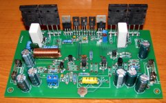
1. Test all your components for defects including PCB (Note on this PCB there is one jumper)
2. Stuff PCB starting with small components working your way to large components i.e. output transistors
3. Examine assembled unit for any solder issues or bent pins shorting others
4. Attach assembled unit to PCB isolating the transistors from heat sink.(Test this)
5. Ensure bias trim pot is set for maximum resistance
6. Attach bulbs on positive and negative rails
7. Do a jig then power up, if bulbs light up, wash rinse repeat, you may have done this in poor light
8. If all goes well, set bias, attach scopes and torture amplifier, if it holds up
9. Plug in your speakers (some use speaker protection)
10. Plug in the "I like to move it move from Madagascar" CD
11. MOVE IT !!!!!!!!!!
12. WE LIKE TO............
It should be fine.
Bias is about 46mV across both emitter resistors.
i'm sorry which are the emitter resistors? R17, R10?
Heres how I do it.
4. Attach assembled unit to PCB isolating the transistors from heat sink.(Test this)
6. Attach bulbs on positive and negative rails
7. Do a jig then power up, if bulbs light up, wash rinse repeat, you may have done this in poor light
8. If all goes well, set bias, attach scopes and torture amplifier, if it holds up
I just want to clarify lol
Questions:
4. Are all transistors isolated from the heat sink? Am I to take this as i shouldn't ground them to the heat sink? lol
Got to use some isolation pad that transfers heat?
6. You literally mean light bulbs to see if power turn on from the PSU? Bulbs attach to the SYMEF power rail? hehe
7. done it in poor light?
lol8. I don't have a scope at home :/ just a True RMS multimeter with a crap load of features including frequency and duty ratio measure :/
I can hook up a 6.5" driver/speaker to it that i dented and test with that. Make a low pass filter for it and hook up to the SYMEF and see if it sings? is that torture enough? lol
Hi Digger,
1. From schematic on site: R13,R14,R24,R25.
2. Yes use isolation pads to prevent short circuits
3. If you have a variable power supply, that will work too
All the best
Thanks for those clarification OnAudio
for the PSU, what power requirements do you recommend?
As per the website shchematic you need +40V and -40V and you state that the amp can do 150W into 4 Ohm.... that will put you somewhere around 300VA Toroidal Transformer and each 40V secondary will suck around 1.875A. That's borderline minimum and once you put in for a bit of safety (20%) it gets you around 380VA and losses...400VA?
I found this Avel Y236853 625VA 40V+40V Toroidal Transformer, will it do the trick? hehe
What are the tolerances on the +40V and -40V? Can it be 35V-45V?
Thanks
fyi.
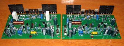
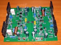
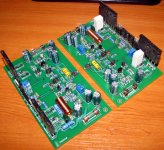
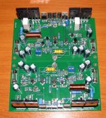
I just got the two PCBs
.....and second channel
.......stil missing few components , next week I hope to finish PCB's
Thank you Harrison ..........
.......stil missing few components , next week I hope to finish PCB's
Thank you Harrison ..........
Attachments
What do you guys think about this transformer?
AS-4440 400VA Audio Toroidal Transformer
AS-4440 400VA Audio Toroidal Transformer
What do you guys think about this transformer?
AS-4440 400VA Audio Toroidal Transformer
NOOOO! It will fry your SYMEF!
Get a transformer that will deliver 30-0-30 (or as low as a 27-0-27). Multiply by sqrt(2) to get RMS DC voltage. (which in the case of 30-0-30 turns out to be 42.4-0-42.4) Subtract the Vf of the diodes in the rectifier bridge (min 1V) and you're somewhere around (above) 40-0-40 (DC). Mind you, this is under load. Idle voltage will be higher. To account for this you can:
A) Put some zeners (39V) between GND and +/-40V (induces diode switching noise)
B) Put some 5W resistors (470 ohm) between GND and +-40V (will give 2 x 3.4 W load at all times at the expense of heat)
C) use a regulated power (costly at these currencies, switching noise)
But don't use a 40-0-40 transformer!!!
I'm in the process of sourcing a PSU myself:
a) Is 40V absolute maximum (should I get 25-0-25 or 28-0-28 instead of 30-0-30)??
b) I'm looking at building a Dual mono-config, will 250VA x 2 be OK or should I get 2 x 300VA?
suggested supply is 40v.
Oooooh.....yes! I have made torture test using 2x 6.5 inches of speaker with a total impedance of 6ohms.mind you again, that the impedance that makes the amplifier put into stress and not the size.....
regards,
joel
p.s.
when I said 40v that is D.C. rail supply.
Oooooh.....yes! I have made torture test using 2x 6.5 inches of speaker with a total impedance of 6ohms.mind you again, that the impedance that makes the amplifier put into stress and not the size....
.regards,
joel
p.s.
when I said 40v that is D.C. rail supply.
Last edited:
30v x 1.4 -1 = 41volts DC
regards,
joel
I think that's the same equation I used on the previous page..
So that looks correct to me.
I was under the impression that the Voltage numbers (eg. 30-0-30) are given @ the specified rating (eg. 300VA), and that sometimes idle voltage can be a little higher (to account for resistance in the coil) Vunloaded = Vloaded + I*Rc.
Quality toroids will use nice thick wire and have very low Resistance, but a few volts can be expected (depending on rating).
Am I wrong?
@ Digger
This is much better Antek - AN-5230. I know someone using +/- 60VDC with 8 ohm load however I like a large safety margin. +/- 40VDC to +/- 50VDC keeps you safe and helps the amplifier drip honey all the way.
@ Alex.
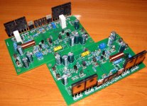
Great progress
This is much better Antek - AN-5230. I know someone using +/- 60VDC with 8 ohm load however I like a large safety margin. +/- 40VDC to +/- 50VDC keeps you safe and helps the amplifier drip honey all the way.
@ Alex.
Great progress
- Home
- Amplifiers
- Solid State
- SYMEF amplifier