Hey Banat,
Have you analyzed the swing needed?
Swing from the driver will be a limiting factor with the LTP and DC-connection.
You must take very opportunity you can to maximise it.
Even when bootstrapped and with ECC99 grid referensed to ground the driver will not be far from clipping before the outputstage.
Unfortunately 1,6k Ra-Ra seems to be on the high side and will probably not even give 10W out.
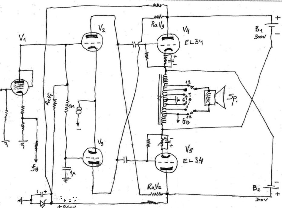
In simple Circlotron schematic ( Ecc99 & 2x EL34 ) you can determine needed voltage swing by varying driver anode resistors , by varying LTP 100k trimpot you can adjust input voltage treshold before clipping .
LTP will achieve allmost 100% of driver stage AC balance which is important for Circlotron correct performance , this old style bootstapped driver stage is here allways integral part of output Circlotron power stage , without anode bootstrap driver stage well need around 600-700 VDC supply to drive correct Circlotron power stage , since Circlotron is basically formed from two CF .
1,6K is here actually Rk-Rk impedance not Ra-a` , 1/4 of impedance of convetional OPT Ra-a` .
Best Regards !
Last edited:
Hey Banat,
I know all the theory, just wanted to know if you had calculated") . Still not the best solution, in my opinion, with only ca 100V Ua over the ECC99.
. Still not the best solution, in my opinion, with only ca 100V Ua over the ECC99.
Splitting hairs with Ra resp Rk? It wasn´t what it was about. 1,6k is to high to get optimal results from this design.
I know all the theory, just wanted to know if you had calculated
. Still not the best solution, in my opinion, with only ca 100V Ua over the ECC99.Splitting hairs with Ra resp Rk? It wasn´t what it was about. 1,6k is to high to get optimal results from this design.
Last edited:
you are not very optimistic
well, whatever, a 40watt might clip at 15watt too
but if it clips at 15watt, I would consider that very good, actually
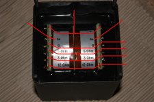
will it matter which tap I use for speaker out
I have 12-8-6-0 / 0-6-8-12 ohm
btw, primaries are 0-800/0-800 ohm, 1.6ohm P-P
and its air gapped C-core
a bit much for this, but whatever, Im happy if it works at all
much thanks to Banat
cheers
well, whatever, a 40watt might clip at 15watt too
but if it clips at 15watt, I would consider that very good, actually
will it matter which tap I use for speaker out
I have 12-8-6-0 / 0-6-8-12 ohm
btw, primaries are 0-800/0-800 ohm, 1.6ohm P-P
and its air gapped C-core
a bit much for this, but whatever, Im happy if it works at all
much thanks to Banat
cheers
I kept back for most of this.
But I just can't let this go:
Especially with a Circlotron style circuit,
where voltage references to ground may be ambiguous,
you absolutely must avoid an auto-transformer.
This is a death-trap,
just waiting for some child to tug a speaker-cable.
D.C. voltages stored in powersupply are just looking to empty themselves through some unforeseen or accidental connection.
The windings in the autotransformer will simply conduct DC.
Hydro would ban this, as would UL .
This will neither be legal nor moral.
Your second circuit is not much better.
This one also breaks the cardinal rule,
of keeping HV idle currents out of the secondary to speaker outs.
With a standard transformer you have 1kV of insulation/
protection from HV leaking to speaker lines.
This circuit defeats all the careful safety features of well-designed output circuits.

Please find a way to make it safe.
The original Circlotron had 2 kV transformer isolation from HV, in case of cap failure.
Look again - Think again:

But I just can't let this go:

Especially with a Circlotron style circuit,
where voltage references to ground may be ambiguous,
you absolutely must avoid an auto-transformer.
This is a death-trap,
just waiting for some child to tug a speaker-cable.
An externally hosted image should be here but it was not working when we last tested it.
D.C. voltages stored in powersupply are just looking to empty themselves through some unforeseen or accidental connection.
The windings in the autotransformer will simply conduct DC.
Hydro would ban this, as would UL .
This will neither be legal nor moral.
Your second circuit is not much better.
This one also breaks the cardinal rule,
of keeping HV idle currents out of the secondary to speaker outs.
With a standard transformer you have 1kV of insulation/
protection from HV leaking to speaker lines.
This circuit defeats all the careful safety features of well-designed output circuits.
Please find a way to make it safe.
The original Circlotron had 2 kV transformer isolation from HV, in case of cap failure.
Look again - Think again:
Last edited:
Connect with secondary separate(not auto) and parallell the two windings. Take the signal from the 0-12ohm tap with 0 to ground. You will then get something like 12W with 300V.
ahh, sounds fine
like this ?
Attachments


- Status
- This old topic is closed. If you want to reopen this topic, contact a moderator using the "Report Post" button.
- Home
- Amplifiers
- Tubes / Valves
- Circlotron questions