I have build the SE wire with LM4562 and as less as possible smd parts.
With the dip8 socket i can also try other opamps.
It sounds great with my AKG K701.
I have also pcb design and filmdesign on pdf.
DC offset at output < 1mV, just great.
With the dip8 socket i can also try other opamps.
It sounds great with my AKG K701.
An externally hosted image should be here but it was not working when we last tested it.
I have also pcb design and filmdesign on pdf.
An externally hosted image should be here but it was not working when we last tested it.
DC offset at output < 1mV, just great.
Last edited:
can we please stay vaguely on topic here? koifarm your amp is not the wire, it is not even close. you have used the same buffer to make a headphone amp and that is where the similarity ends.
this is the build thread for a specific range of headphone amps by opc, not somewhere to display any buffered opamp design. sorry I dont mean to be rude, its just that weve had another thread started calling the amp the wire as well. it used the opa1632 and thats where the similarity ended because he, like you had an irrational fear of SMD, but was determined not to let that stop him make an amp called the wire; I guess because it has been so popular? I told him the same thing, so he started another thread and called the amp 'the pipe' now you, its weird, I guess opc should be flattered
the wire is a tiny, very high performance 3 layer design using all SMD parts and caps that decouple everything connected to the power/ground planes directly from the pins and thus pretty much doesnt have any traces, just pcb layers and vias. doesnt have a pot or onboard supply.
your amp is comparatively huge, avoids SMD, uses different opamps, has a pot and an onboard power supply
and its designed by you, not opc
Last edited:
can we please stay vaguely on topic here?
Yes Sir...

I might type out a comparison review between the Wire se-se and O2 soon[ish]. I've had long enough to get used to both and do a few comparisons, though no DBT as yet.
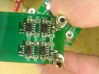
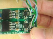
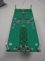
SMD fault finding
Time for some photos of noob SMD work ...
-10.5VDC on the output of the channel with parts numbered in single digits. The other side of the board has only single digit mV DC on the output.
Looking at the photos now R1 looks a lot worse than it did by eye. Also I've already removed the washers that were on the standoffs in those photos, I noticed they are just touching on R10 and R3. I've already put a bit of flux on all of the components on the 'bad' side of the board and still got same result. Obviously something's still pulling the output to the negative rail somewhere.
PSU board works fine and is set at +/-12VDC.
qusp, ignore the dodgy wire it's all I've got on hand and something more suitable was supposed to have arrived last week but should be here in the next few days.
Attachments
No need ... redid R1 and C8 and it is back to 2 or 3mV DC and 0.5mV on the other channel.
Need to wire up the i2s to the DAC before I have any chance of hearing anything though!
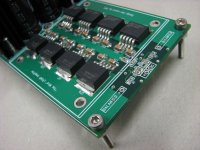
Good to have some of opc's boards back in here again amiright? This is the most recent BAL-SE for those playing along at home, probably should have mentioned that above.
Need to wire up the i2s to the DAC before I have any chance of hearing anything though!
Good to have some of opc's boards back in here again amiright? This is the most recent BAL-SE for those playing along at home, probably should have mentioned that above.
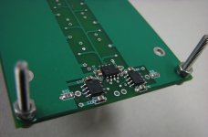
see I dont know if youve been taking cues from opc, or if its just lack of SMD practice, but till youve got some experience I would avoid filling in the vias like that. I think thats the source of your problem. C4 and R5 should not be joined. in fact none of the junctions C18->R7, C14->R11, C8->R1, C4->R5 should be bridged. the others along the front (C17->R10, C13->R9, C7->R4 C3->R3) if you look at the schematic are ok, as the decoupling caps go to the ground via as do the input resistors, but the inner ones the decoupling cap goes to ground, but R5, R1, R11, R7 do not connect to ground on either side; R5 is your problem the others appear to be ok, but I would clean with a wick just in case
edit yeah couldnt see if R1 was bridged in the same way, looked touch and go, I for sure wouldnt connect anything before cleaning that lot up
edit yeah couldnt see if R1 was bridged in the same way, looked touch and go, I for sure wouldnt connect anything before cleaning that lot up
Last edited:
Hi Hochopeper
There's no question that R5 and C4 were shorted in that picture, and I'd guess that's what the problem was.
As qusp mentioned... just clean those up a little with some solder wick and some flux, and you should be good to go.
As you no doubt learned from this, the camera is a really powerful tool if you don't have a microscope. Just take a few good macro photos in good light and you'll be able to clearly see what might be difficult to see with the naked eye.
Those vias are close to the other pad, so it's easy to get a solder bridge where one doesn't belong!
Cheers,
Owen
whats
As qusp mentioned... (<-this about?) haha,
I wasnt critiquing your soldering mate, just i've noticed you almost always fill in vias in a deliberate manner, while I do sometimes but not always, depends. I know you use a larger chisel tip than me so thats possibly just a biproduct of that and its not a bad thing, just something I would avoid doing deliberately till you get the hang of SMD and reading SMD PCB boards.
for instance i've done it on the LPUHP buffer decoupling as its a higher current board. just finishing up one board now, need to wait till another LT1033 gets here before I do the other one.
oh and BTW I have some listening impressions of the bal-bal and some nutty test dac build pics i'll post tomorrow night. but I can say one thing, the bal-bal is all that i'd hoped for and for my application doesnt need heatsinks at all, although I do like the copper wings I made so they will probably stay on that board
Last edited:
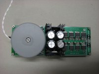
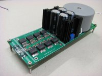
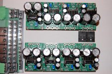
is this the worlds highest performance high power headphone amp? I guess we'll see
came together pretty well, needs a bit of cleaning up, waiting for the LT1085/1033 for the second board to arrive and possibly the heatsinks before I can say
came together pretty well, needs a bit of cleaning up, waiting for the LT1085/1033 for the second board to arrive and possibly the heatsinks before I can say
Attachments
-
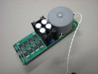 the wire LPUHP first channel_01May2012_0904.jpg148.8 KB · Views: 555
 -
 full the wire LPUHP first channel_01May2012_0869.jpg153.6 KB · Views: 545
 -
 yes the wire LPUHP first channel_01May2012_0866.jpg175.7 KB · Views: 542
 -
 the wire LPUHP first channel_01May2012_0875.jpg119.7 KB · Views: 540
 -
 diff in the wire LPUHP first channel_01May2012_0878.jpg117.9 KB · Views: 533
 -
 the wire LPUHP first channel_01May2012_0893.jpg182.4 KB · Views: 182
Last edited:
The MOSFETs have arrived!
Now what do I do with the power supplies...
indeed, mate, i've had my mosfets for months and I dont know what to do, been waiting for results, as it will make an extreme difference to the casework for a multichannel amp, looks like you have a similar problem
Looks good!! I'm glad they arrived safely. It's always so quick from here to the GTA!
I'll do my best to get the supply measurements posted tonight... I've been putting off staying late at work because I've been swamped, but hopefully I can get around to it.
If not tonight, then definitely over the weekend.
Regards,
Owen
I'll do my best to get the supply measurements posted tonight... I've been putting off staying late at work because I've been swamped, but hopefully I can get around to it.
If not tonight, then definitely over the weekend.
Regards,
Owen
Yes, we are all curious about the power supplies measurements, but my question wasn't meant to put more stress on Owen. I already know that both technologies will deliver excellent results, and that neither one is perfect.
I haven't decided for myself what is the reasonable trade-off between cost and performance. Building 8 completely independent power supplies looks like over-engineering. I will be using the amplifiers to build two four-way active speakers. Perhaps using one power supply per speaker will be good enough. Another option is to use one power supply for the base channel where the power demand is huge, and another shared power supply for the midrange and treble channels. Two power supplies per speaker is economically more reasonable.
I haven't decided for myself what is the reasonable trade-off between cost and performance. Building 8 completely independent power supplies looks like over-engineering. I will be using the amplifiers to build two four-way active speakers. Perhaps using one power supply per speaker will be good enough. Another option is to use one power supply for the base channel where the power demand is huge, and another shared power supply for the midrange and treble channels. Two power supplies per speaker is economically more reasonable.
Last edited:
is this the worlds highest performance high power headphone amp? I guess we'll see
I don't mean to be an antagonist but the opamp gain stage is a limiting factor, there is not enough voltage swing to power the HE-6 anywhere near 6 watts. The opamp loses linearity around 8 Vrms, that just gives a little over 1 watt into 50 ohm HE-6, consensus is we need 6 watts for the HE-6. Probably be OK for the more effecient HE-500's, but barely.
The buffer stage is certaininly impressive, but we have to use an opamp gain in order to not have DC offset correct? Just trying to think out of the box on how to make this a 6W into 50 ohm amp.
- Status
- This old topic is closed. If you want to reopen this topic, contact a moderator using the "Report Post" button.
- Home
- Amplifiers
- Headphone Systems
- THE WIRE conglomerate build thread, impressions and gallery