I wonder how many people will actually bias to Class A @ 100W???
Eventaully, I'm planning to go as high as 150 or 200 watt Class A with at least 500W class AB, in my ultimate version of F5T, if everything goes fine, because that would be intended for full range electrostatic speakers.
With heatsink I have (4 of conrad MF35-151.5) and transformers ( pair of 22V dual 400VA) ( all intended for other projects which got scrapped as soon as Papa published F5T
") ), I could go only to 60watt at 4 ohm single ended. But it would be good enough for a starter, since my normal F5 only give 13W or so Class A to 4 ohm!
), I could go only to 60watt at 4 ohm single ended. But it would be good enough for a starter, since my normal F5 only give 13W or so Class A to 4 ohm!There are a lot of very capable people here in this site, and I thought I would not be qualified to do prototyping. I have successfully built F1 and F5, but no balanced amp yet. But Tea-Bags comment is encouraging me a bit.
I'd be interested in trying V3 input and single output boards with PSU. I'd prefer a larger cap boards, but can do with 16 caps board if that is only thing offered. Problem is I do not have fairchild devices and at the moment am not aware of source for matched quads.
Last edited:
Hey Ihquam,
I was thinking about up a similar forced air build. Where did you get the heatsink simulation software from?
Thanks,
Steve
This URL gets you to the website for the software: Frigus Primore - Thermal Design for Electronics. There are 2 programs: NatSink is for natural convection heatsinks. Hsink is for forced air heatsinks.
200 watt Class A with at least 500W class AB,... offered.
Woohahaha !
(excuse, me had spontaneous hysterical frenzy attack)
Hi Horio,
I'm probably wrong here, but at given heatsink capacity and given transformer VA rating, wouldn't single ended better in getting higher class A power, while balanced better in getting better overall power? Even though you get to use lower rail voltage at given overall taget power with balanced so higher bias current per device at given heatsink and transformer capacity, in SE mode 4 pairs of devices are in pararell adding up the current, while in balance mode there are only 2 of 2 pair devices in parallel to add the current against speakers? I'd appreciate your correction if I'm wrong.
Thanks!
I think in the end its really about the same thing, but you don't have to cascode the balanced setup thanks to the lower rail voltages.
Woohahaha !
(excuse, me had spontaneous hysterical frenzy attack)
Yea I guess i deserved that but... What kind of major huddles do you expect one would have in achieving such power, if one has heatsinks like that of Pass XS series and really big transformers, Jacco?
not aware of source for matched quads.
A few of us with some of these FETs or resources to these gets are co-operating to get these out in somewhat reasonable manner. the demand appears high but the supply is shaky.
I can supply a matched quad currently to someone who agrees to the protos for UKT or matched pairs more easily. I have a small stock of pairs, and have 1000 unmatched P-channels waiting for their complementary partners.
Someone building the V2 I can donate some matched pairs to the cause.
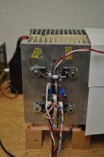
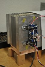
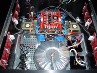
Here is today's experiment with a balanced F5 on 1/2 E007 at about 108 watts dissipation. The boards are Cviller v1.2 F5 boards from the DIYAudio Store. One of the boards has the polarities of all active devices swapped so that rails voltages are directly strapped from board to board.
The design is for rails voltages of 17.6V and bias of 1.7A per MOSFET. Output power should be around 46 watts. Currently I cannot run it above 1.5A because of limitations of my bench power supplies. With these limitations the 1/2 E007 heatsink is only rising about 20C with 108 watts, being cooled with a Noctua NF-S12-800 fan (800 rpm, 59 cu-meters/hr airflow). The heatsink must be cut in half before I can believe the temperature rise measurement.
I fired it up today. The 2nd harmonic was adjusted to a minimum in bridged-mode (ie. the JFET source resistors grounded) . The THD measurements directly follow the curves in Nelson's F5 Manual.
The idea is to make an identical copy on the other half of the E007 heatsink, placed fin-to-fin to form a heat tunnel. This will provide a compact 40+ watts class-A per channel balanced stereo amplifier.
Attachments
Hey Ihquam,
Great Site -- thanks
Steve
Great Site -- thanks
Steve
This URL gets you to the website for the software: Frigus Primore - Thermal Design for Electronics. There are 2 programs: NatSink is for natural convection heatsinks. Hsink is for forced air heatsinks.
I wonder how many people will actually bias to Class A @ 100W???
Andy,
my last XA built was app. 120-140W Class A.
The F5X I plan to build with your boards will be something between 60-100W (120-200 peak) into 8 ohms class A.
I use Aavid Heatsinks 4 per Monoblock, 210mm height. No Problem with the heat transfer.
I would love to assist with beta testing but then it would be finished next year. I simply don't have time. I visit this thread every 3 days or so.
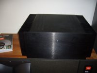
Believe it or not, i have a pair of JBL Everest standing here for 3 weeks now and I din't find time to set them up.

Attachments
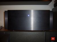
JBL post up pics of that beast (xa) .......
Could find only these. It's a modded Hifi2000 enclosure.
Off to work....
Attachments
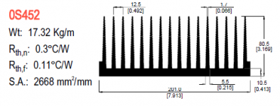
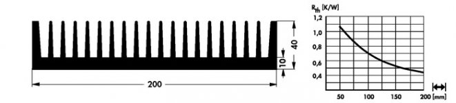
Modushop mentions 0.28C/W for 2 heatsinks lined up (210mm length) , sounds a little optimistic.
Placing two heatsinks side to side drops efficiency, so a single heatsink would have to do lower than 0.56C/W
For 25C above ambient, i wouldn't try to get more than 150W from a 5U case.
Fischer SK47 (non-corrected for lower temperature operation), baseplate is a few mm thicker than the Modushop one=>
Attachments
Last edited:
Could find only these. It's a modded Hifi2000 enclosure.
Off to work....
JBL , Those sinks look kinda small for 100w+ of class-a
hurdles, ?
Depends how the 200W Class A is defined, peak value or continuous.
Leaving Class A at 200W peak translates to 500 Watts dissipation, for 200W continuous it would be around 700, per channel.
Without access to a heatsink that's optimised for some 100W dissipation each, at a ballpark figure height of some 10 inches, a natural convection monaural will become pretty voluptuous (aka Fat Betty).
A source for affordable big can electrolytics with >100V rating (125V surge) would be a big help.
Frankly, i have trouble to understand why anyone would be willing to spend so many dollars on such an amp design.
An X600 in X1000 dress, with lower rails and higher bias level, is more elegant, more to the point for such an expenditure (and you'll have more backup during the build).
Last edited:
JBL , Those sinks look kinda small for 100w+ of class-a
Good joke
Dissipation is 260W per channel and I measure app. 45°C.
Don't know how you claculate but these mono chassis (4 of these heatsinks) have 0.07 K/W
Last edited:
- Status
- This old topic is closed. If you want to reopen this topic, contact a moderator using the "Report Post" button.
- Home
- Amplifiers
- Pass Labs
- F5 Turbo Circuit Boards