I am fairly new to this.
Can anyone help me setup a switch mode power supply to test my pcb with. I have everything populated but when I go to hook it up...the way i think is correct i can't seem to get -24 volts? I seem to get +24 fine.
Where do i connect the ground wires on the pcb directly to psu? pcb ground to chassis.
any help is appreciated
Greetings.
I will try to attach photos... see attached
power supply is UAW250S:
http://www.cosel.co.jp/en/products/pdf/SFE_UAW.pdf
It is aleph J pcb I want to start up
I will try to attach photos... see attached
power supply is UAW250S:
http://www.cosel.co.jp/en/products/pdf/SFE_UAW.pdf
It is aleph J pcb I want to start up
Attachments
It's only a single 24V supply so you would need two of them to provide + and - supplies.
I note you already have two of them, I presume you have one for each amp.
I have to assume that the outputs are electrically isolated from each other.
Try connecting V+ of one to V- of the other and use this common connection for 0V. Then use the unused V- and V+ as your -24V and +24V supplies.
I note you already have two of them, I presume you have one for each amp.
I have to assume that the outputs are electrically isolated from each other.
Try connecting V+ of one to V- of the other and use this common connection for 0V. Then use the unused V- and V+ as your -24V and +24V supplies.
Last edited:
Thanks for everyones replies.
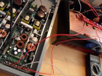
I will look for a single dual power supply.. I have two of these 1u power supply but i do not want to use two because it will be too big for my chassis unless i mount into seperate chassis like in the photo it now looks big and ugly LoL
Again thanks I will try Kate and Dad's suggestion first.
I will look for a single dual power supply.. I have two of these 1u power supply but i do not want to use two because it will be too big for my chassis unless i mount into seperate chassis like in the photo it now looks big and ugly LoL
Again thanks I will try Kate and Dad's suggestion first.
According to the datasheet these SMPS's are single output.
Your last picture shows FG (frame ground) connected aswell as + and -.
To hook up the right way is to connect the + from one PS unit to the - of the other. This connection will be GND for the amplifier! Then take + from one and - from the other unit (those that were NOT used to connect GND).
Pls check the SMPS frame if it is connected to the -. If this is not the case then proceed. The FG terminals connect to earth.
If the case is connected to - then one PS must be mounted insulated.
The nature of these beasts is that normally the -ve will be connected to the chassis - not always but its common.
Just measure between V+ and chassis and V- and chassis with a DMM.
If they are open circuit you are laughing. If not then you will have to insulate one PSU from the chassis. Not a problem just use insulating standoffs and nylon bolts.
The PSU that you use for the +24V can be mounted normally, it is the PSU that you want use for the -24V that must be isolated from Chassis GND as you will be connecting its +V to the Chassis and using its -V as -24V.
Last edited:

I don't think this belongs in the Pass domain ??
I'll post a small video of it (NP aleph J) running on youtube then thread can be closed/moved?
I also have another question as for RCA input... do I bridge -In to ground?
Thanks again guys not too much BS around here today
Now I get -24v and +24 to the pcb but no sound.. gah... i wonder how i bridge the input of rca?
yes
neg in to gnd
RCA hot to pos in
no sound, what should i check i have signal to the +In.
- Status
- This old topic is closed. If you want to reopen this topic, contact a moderator using the "Report Post" button.
- Home
- Amplifiers
- Pass Labs
- switching power supply.. can't get -24v?