*facepalm
yes you're right... but found another fault on the board..... seems that if i connect the left side of the board i get 50 v from + to- but nothing from- to gnd??? se underside of board??? seems to me that there r something not cut away...
will resolder to other side and see.
thank
digging hole to china and going to bury myself....... so emberrased...I think, 50 VDC you got from V+ and V-? not from V+ and Gnd or V- and Gnd,..Do you?
yes you're right... but found another fault on the board..... seems that if i connect the left side of the board i get 50 v from + to- but nothing from- to gnd??? se underside of board??? seems to me that there r something not cut away...
will resolder to other side and see.
thank
Last edited:

only psu connected at this time.
1. colors:
pri is blu and brown
sec1 is red black
sec2 is orange yellow
tested psu + to gnd is 24,9v
- to gnd is 25.0v
so guess this is ok for now. wires will be changed and twisted when amp is fired up and stable. will also shield trafo.
going to make bulb tester... or can i use an Amperemeter around 1 fase (live)
thanks
first - search for "bulb tester" ( AndrewT is strong proponnt of that tool , with reason) ;
make one
connect amp via BT (say that 40-60W is good for start)
disconnect amp pcbs from PSU and test just PSU
from pics I see that you connected Graetzs as needed - check polarity 3 times before powering up!
power up and measure voltage on each output
BT will lit brightly and dim after sec-2 if everything is OK
if BT is bright for prolonged time , something is wrong
measure voltage between each + and gnd - you can expect DC voltage in range Vac x 1.41
measure voltage between each - and gnd - same voltage ( opposite polarity , off course)
example - for 18Vac secondaries , you can expect 18x1,41~25Vdc
when you are done with that , report here
but first !! write what wire colors are written on xformer - we need to check did you connected secondaries as needed
- to gnd measures 25V
+ to gnd measures 24.9V
You must specify +- and whether dc or ac.
I would expect to see + to gnd showing +24.9Vdc
and - to gnd showing -25.0Vdc
If your meter read + for both supplies, then you must have mixed up (swapped) your test probes.
Primary.
Blu is to Neutral
Brn is to Live.
But in mains wiring you must consider both L & N to be equally dangerous.
Due that condition, both L & N are insulated to the same standards.
This allows one to swap the transformer Blu & Brn to the "wrong" terminals. Some times a transformer behaves/performs slightly better when wired up "correctly" and sometimes when wired "wrong".
But ensure the mains fuse is still in the LIVE side.
Last edited:
ok. BT complete. connected and it litt up in 1-2 sec and turned off.
so now I guess I shold connect the psu to main board?
so now I guess I shold connect the psu to main board?
OK - for now everything is fine
you can proceed ( with BT ) with output connected
I'm not familiar with these pcbs , so I can't check visually is everything connected as needed
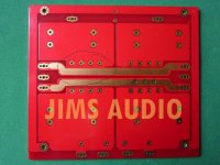
http://dl.dropbox.com/u/57077275/downside fualt.jpg
is it this u see??
is it this u see??
I see, seem the negative rail connected to ground...If yes, cut it...cutter will work easy..")
You r correct.+24.9 and -25
and my dayjob is doing electrics in houses so primary side is no worry
and iec con. has fuse. slow 3A.
and my dayjob is doing electrics in houses so primary side is no worry
and iec con. has fuse. slow 3A.
- to gnd measures 25V
+ to gnd measures 24.9V
You must specify +- and whether dc or ac.
I would expect to see + to gnd showing +24.9Vdc
and - to gnd showing -25.0Vdc
If your meter read + for both supplies, then you must have mixed up (swapped) your test probes.
Primary.
Blu is to Neutral
Brn is to Live.
But in mains wiring you must consider both L & N to be equally dangerous.
Due that condition, both L & N are insulated to the same standards.
This allows one to swap the transformer Blu & Brn to the "wrong" terminals. Some times a transformer behaves/performs slightly better when wired up "correctly" and sometimes when wired "wrong".
But ensure the mains fuse is still in the LIVE side.
Ill be happy to change them if it bothers you or someone else please direct me to where i could get some.
already scrapped other boards from jim because of copyright issues... (aleph x)....
No longer going to say I'm sorry, even if I am.... already done that and supported diy for my mistake.... didnt know better when i bought them... and now I really want to get some progress before I need to get another hobby.....
or someone else please direct me to where i could get some. already scrapped other boards from jim because of copyright issues... (aleph x)....
No longer going to say I'm sorry, even if I am....
already done that and supported diy for my mistake.... didnt know better when i bought them... and now I really want to get some progress before I need to get another hobby.....oh man, jims audio boards now also in BA-2 thread
ok everything hooked up. when starting the bulb gives of bright light then turns off. so what should I messure now?
if everything is connected as intended to be - between small bias pcb and big ones , you can proceed
edit : that connection is needed there
if you're measuring voltages as you wrote - everything is OK with PSU pcb
You r correct.+24.9 and -25
........
voilla
pcb is certainly OK , then ......
- Home
- Amplifiers
- Pass Labs
- Burning Amplifier BA-2