This might seem like nit picking, but I wouldn't class any new design as a Unity horn. The Synergy name relates to the concepts covered in the patent, rather than whether it is a 2 way horn or a 3 way.
Regarding coverage, reducing the angle makes things more difficult because it becomes harder to fit the mids on the side walls, the width is more critical than the length. You need to start using smaller mids or using an awkward overlapping arrangement, or even a mix of both. It seems like Danley likes a 50 x 50 coverage angle as that is what he uses in his flagship SH50, which is apparently the one he uses at home. It would be a workable compromise.
My S1 with the 4 mids was based on the Unity kit, it was made a little larger and did not have the second flare angle. Ports were 18mm diameter x the depth of the 18mm MDF and placed 86mm from the throat along the central axis.
The Synergy horns vary greatly, obviously Danley has to make them cater to many different situations. One of them is 25 x 25 degrees, others are as wide as 100. Wider dispersion also means less bottom extension. So if you start with a 60 x 60 with 4 drivers, that can work fine, 5" mids will fit on the sides and give you a 1k xo with extension to around 250 Hz. Now if you want wider, you lose the extension so you have to add more drivers. 90 x 40 with 6 of the same mids seems to be a workable compromise, which is what I did with my S2:
Now what would be more interesting is to see an Akabak model of S2, which is 90 x 40 with 6 drivers. I've measured the horizontal dispersion and it's very good:
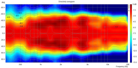
It would be interesting to see how accurately Akabak could sim it, including off axis angles.
So I'm now planning S3 with the Celestion 4" mid and a higher crossover, slightly smaller ports and possibly slightly narrower coverage. Perhaps 40 x 80. Plans are in progress for a group buy with the Celestion mid to fulfill a minimum order. Anyone interested should send me a PM or a message via the contact link on my blog.
Regarding coverage, reducing the angle makes things more difficult because it becomes harder to fit the mids on the side walls, the width is more critical than the length. You need to start using smaller mids or using an awkward overlapping arrangement, or even a mix of both. It seems like Danley likes a 50 x 50 coverage angle as that is what he uses in his flagship SH50, which is apparently the one he uses at home. It would be a workable compromise.
My S1 with the 4 mids was based on the Unity kit, it was made a little larger and did not have the second flare angle. Ports were 18mm diameter x the depth of the 18mm MDF and placed 86mm from the throat along the central axis.
An externally hosted image should be here but it was not working when we last tested it.
The Synergy horns vary greatly, obviously Danley has to make them cater to many different situations. One of them is 25 x 25 degrees, others are as wide as 100. Wider dispersion also means less bottom extension. So if you start with a 60 x 60 with 4 drivers, that can work fine, 5" mids will fit on the sides and give you a 1k xo with extension to around 250 Hz. Now if you want wider, you lose the extension so you have to add more drivers. 90 x 40 with 6 of the same mids seems to be a workable compromise, which is what I did with my S2:
An externally hosted image should be here but it was not working when we last tested it.
Now what would be more interesting is to see an Akabak model of S2, which is 90 x 40 with 6 drivers. I've measured the horizontal dispersion and it's very good:
It would be interesting to see how accurately Akabak could sim it, including off axis angles.
So I'm now planning S3 with the Celestion 4" mid and a higher crossover, slightly smaller ports and possibly slightly narrower coverage. Perhaps 40 x 80. Plans are in progress for a group buy with the Celestion mid to fulfill a minimum order. Anyone interested should send me a PM or a message via the contact link on my blog.
When you mount your midranges to your horn, where are the holes located in relation to the driver? IE, are the holes right in front of the woofer surround, or are they closer to the edge?
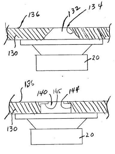
In the Synergy horn patent, the holes are located in the center
In a Lambda Unity, the holes seem to be nearly at the very edge of the basket
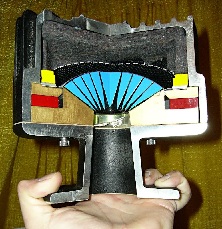
In an SH-25 the frustrum is located squarely in the point of the cone where the depth is the greatest
In a compression driver, we see a verrrrrrry smooth transition from the diaphragm to the throat.
Here's why I bring this up:
Over the weekend I built a pair of Synergy horns with a phase plug for the midrange driver. And the phase plug worked so well, I had to double check to see if my compression driver was connected. (IE, it sounded like it was connected and it wasn't!!)
So the phase plug seems to extend the response quite a bit.
The downside is that the lower treble is pretty rough. I haven't done any measurements on it yet, so at this point, the roughness could be one of four things:
Either way, phase plugs seem to work in a Unity.
So I am thinking that we may get good results if we can come up with a way to create a verrrry gradual transition from the surface of the midrange cone to the body of the horn. If you look at the pictures of the SH-25 you'll notice that this was done for the 8" woofers in particular. The mounting plate is designed to keep the dimensions inside of the woofer chamber small.
For instance, if you're using a 13cm woofer it has a cone that's about 11cm. I know that there's a null that occurs at the center of the cone, due to the radiation from the edges being out-of-phase when they hit the center. Does anyone know if that null occurs at one wavelength, or one half? If it's one half wavelength, then a 11cm cone would have a null at 1545hz, which is consistent with the issues we're seeing. I'm thinking that addressing this geometry might go a long way to extending the high end of our midrange drivers on a Unity horn.
I desperately wish there was some way to simulate this in Akabak, because building a dozen different phase plugs and then measuring them sounds like a full-time job. Even worse, the phase plug will vary from woofer to woofer, due to the geometry of the woofer cone.
If someone has figured out a way to do this in Akabak, I am all ears. There's a PDF file out there with an Akabak model of a compression driver, but the phase plug in that model won't work for us.
In the Synergy horn patent, the holes are located in the center
In a Lambda Unity, the holes seem to be nearly at the very edge of the basket
An externally hosted image should be here but it was not working when we last tested it.
An externally hosted image should be here but it was not working when we last tested it.
In an SH-25 the frustrum is located squarely in the point of the cone where the depth is the greatest
In a compression driver, we see a verrrrrrry smooth transition from the diaphragm to the throat.
Here's why I bring this up:
Over the weekend I built a pair of Synergy horns with a phase plug for the midrange driver. And the phase plug worked so well, I had to double check to see if my compression driver was connected. (IE, it sounded like it was connected and it wasn't!!)
So the phase plug seems to extend the response quite a bit.
The downside is that the lower treble is pretty rough. I haven't done any measurements on it yet, so at this point, the roughness could be one of four things:
- Due to the phase plug, the midranges are playing higher, and interfering with the compression driver
- The phase plug is screwing up the response of the compression driver because it's physically in the way
- My crossover sucks
- All of the above.
Either way, phase plugs seem to work in a Unity.
So I am thinking that we may get good results if we can come up with a way to create a verrrry gradual transition from the surface of the midrange cone to the body of the horn. If you look at the pictures of the SH-25 you'll notice that this was done for the 8" woofers in particular. The mounting plate is designed to keep the dimensions inside of the woofer chamber small.
For instance, if you're using a 13cm woofer it has a cone that's about 11cm. I know that there's a null that occurs at the center of the cone, due to the radiation from the edges being out-of-phase when they hit the center. Does anyone know if that null occurs at one wavelength, or one half? If it's one half wavelength, then a 11cm cone would have a null at 1545hz, which is consistent with the issues we're seeing. I'm thinking that addressing this geometry might go a long way to extending the high end of our midrange drivers on a Unity horn.
I desperately wish there was some way to simulate this in Akabak, because building a dozen different phase plugs and then measuring them sounds like a full-time job. Even worse, the phase plug will vary from woofer to woofer, due to the geometry of the woofer cone.
If someone has figured out a way to do this in Akabak, I am all ears. There's a PDF file out there with an Akabak model of a compression driver, but the phase plug in that model won't work for us.
The acoustical LP filter created by using the “port” holes in the mids reduces harmonic distortion and makes for a steeper acoustical crossover, both good features in a Synergy that a "proper" phase plug would lessen.
In my small format line array the 8” speakers cross over directly to EV DH1AMT with a Paraline coupler.
I wish I had your HF hearing, but since my hearing presently tops out at 15.5 K, the 1.5” exit 3" diaphragms go high enough for me :^(.
Although I ended up placing the two port holes as far to the rear as possible to minimize HF to mid distance and still maintain even center to center port spacing from cabinet to cabinet.
After many tests on the speakers with varying port locations, there did not seem to be much difference in response regardless of the port position.
I tried center and middle positions, as I was hoping for a higher response, peaks and nulls moved around a bit but the upper corner did not change much at all, perhaps 1/4 octave at most, IIRC.
I had many Smaart traces, unfortunately I seem to have thrown them out.
Would have thought there would have been more difference, but it seems what comes out of the port is far more dependent on size and depth and front chamber volume than position. At least that was the case for the Alpha 8 speakers I use for mids.
The routed out perimeter in the SH-25 is likely just to accommodate the excursion of the 8” drivers, I did the same in my cabinets.
Art
Last edited:
I think you can model this very well in Axidriver.
If you feel you're up to it (rough learning curve I've experienced), ABEC2 is the ultimate, this is (from the maker of akabak), akabak and BEM modeler combined; you can really model ANYTHING with this! (But your computer will beg for upgrading).
Oh, and the best thing; it's all FREELY downloadable from the R&D team website, this guy deserves big credits.
Keep up the journey, it brings us all some good food for thought!
Cheers,
Kees
Null will happen at half-wave difference in path lengths from two points driven simultaneously (if that explanation helps).
Patrick B, I ran into an old post of yours considering use of a Jamo closed-back midrange for Unity use. Did anything come of that? I noticed that midrange is on closeout sale for 2bucks right now. Of course the given parameters are about nil. But for 2$ one could tear one apart, measure cone mass, sealed air volume, Qe, etc.
Patrick B, I ran into an old post of yours considering use of a Jamo closed-back midrange for Unity use. Did anything come of that? I noticed that midrange is on closeout sale for 2bucks right now. Of course the given parameters are about nil. But for 2$ one could tear one apart, measure cone mass, sealed air volume, Qe, etc.
In my small format line array the 8” speakers cross over directly to EV DH1AMT with a Paraline coupler.
I wish I had your HF hearing, but since my hearing presently tops out at 15.5 K, the 1.5” exit 3" diaphragms go high enough for me :^(.
Wow, I've never seen your project until today! This is PURE GOLD - there are some things going on here that are incredibly relevant to my preferred environment (car audio).
For instance -
- It looks like you may be able to remove one wall of a horn if you get the wavefront at the throat correct. That has a huge impact on car audio guys, because their horn sizes tend to get a lil' dangerous:

This goes under the dash of a car. If you could remove one wall of the horn you could driver the car a heck of a lot easier. - For ages I've wondered if it was possible to mount compression drivers VERY far from the throat. Like two or three feet away. Theoretically, it seems like it should be possible as long as the dimensions don't exceed the wavelength of sound, and Danley seems to confirm this in a response that he posted to one of your speaker boxes. The ability to do this in a car is very nice because it means you can put the drivers one place and the horn somewhere else.
Here's Danley's post:
PSW Sound Reinforcement Forums: LAB: The Classic Live Audio Board => Mid cone driver slots and holes
Think of a vented box and woofer, one has several things;
First, obviously you have a source that has two phases and one has a 2nd order acoustic low pass filter attached to the rear side of the radiator.
That low pass filter is made from the air in the box, a compliance volume or acoustic spring force (which electrically appears as a series inductance) and the mass of the air in the port (which looks like a Capacitor to ground), hence a 2nd order system.
You can see that relationship if you imagine a ruler clamped to a table, you can see its resonant frequency goes down if you add mass (add a penny at the end / make a longer port or reduce its area) or make the spring weaker (make the ruler longer / or box larger).
When the radiators two opposite phases add, they cancel each other out as they are always 180 degrees apart and of equal magnitude.
The sealed box simply contains one half of the signal allowing the other half to radiate away unhindered.
The low pass filter in a vented box (the vent + box volume) is in the form of a Helmholtz resonator and “at resonance” is an inverter, in other words introduces a phase shift which makes the port radiation “in phase”, additive with the front radiation.
While one doesn’t normally think about this as a “low pass filter” it is. Progressively less comes out of the port as the frequency rises above resonance.
As one lowers the frequency from the resonance (normally the low corner in a vented box), one finds that the phase shift imposed by the L and C reduces towards zero and the sound coming out of the port reaches the same phase angle as the rear radiation.
At this point, this is the “pass” region and the rear radiation increasingly cancels out the front side as the frequency lowers and the vented box has twice the roll off compared to a sealed box.
At a point WAY below Fb, the cancellation is complete.
Above resonance, the output from the port decreases, reverting to a sealed box, which contains the anti-phase rear radiation.
When one has a normal horn, one finds that the radiators rear volume is a sealed box.
At the high frequency corner, one finds that another acoustic “low pass filter” is present although potentially not as obvious.
Here, some portion of the air in the horn throat acts like a lump of mass like a port and some portion of the air between the radiator and throat acts like a compliance or spring, forming a low pass filter.
By sizing the L and C relative to the resistances, one can often extend the hf response by having a suitable low pass filter. As with the vented box, the ultimate roll off is steeper than an unaided alignment.
Here the only output is what comes out of the port (and drives the horn) so to speak.
In the Synergy and Unity horn boxes I designed, I use that “low pass” filter effect to attenuate the distortion products that all drivers produce. The distortion products are 2,3,4,5,6, ect times the fundamental frequency and so to the degree these fall on the rolled off part of the acoustic filter, they are attenuated.
The filter here is made of the volume trapped under the cone and the mass of the air in the port and throat. I don’t use phase plugs here.
Also, when sound is introduced into the horn at some point forward of the apex (such as the cone drivers in our horns), one finds that the upper frequency limit is also set by an additional “low pass” filter effect caused by internal self cancellation.
When the wavelength is short enough (frequency high enough) the sound that went to the pointy end, bounces back and arrives out of phase with the driver pressure.
One finds (as you raise the frequency) that you eventually have a BIG cancellation notch when that “driver to dead end” distance is about 1/4 wl.
The two low pass filter effects strongly attenuate above band energy from the cone drivers and helps make the distortion especially low.
It was that notch, or pondering that notch that made me wonder about and then try what became the Tapped horn.
I thought what happens if I substitute a source of the opposite phase for that reflection? (a source which was present in the back side of the radiator), then they add instead of cancel. Some considerable fiddling in the computer eventually resulted in boxes that work better than similar sized normal bass horns using this new principal.
Anyway, up to now, the only function a phase plug has is to occupy an excess air volume that would have other wise made the acoustic “low pass filter” too low in frequency.
Once one is dealing with a radiator who’s dimensions are approaching the wavelength size, then the other function of a phase plug comes in handy.
The speed of sound governs how a pressure disturbance radiates away from its source.
If one has a radiator that is “large” acoustically and also has a single exit point, one finds that just like in the Synergy and Unity horns, one gets a deep cancellation notch when the difference in the two paths is 1 / 2 wl. The range of coherent summation is limited to the frequencies BELOW the region where cancellation begins.
This is like a pile of subwoofers, when the array is less than about 1/4 wl across, they all add together and feel “mutual radiation pressure” while a significantly larger spacing produces directivity and then lobes.
Here, a phase plug can be shaped so that the acoustic passages all have the same length or have a length appropriate to the desired exit wave front shape.
One big difference in the sound of compression drivers (IMO) after being eq’d flat is that many have a phase plug that produces a converging wavefront at the summation, while what one needs at the throat of a horn is a diverging wavefront. That “clash” can cause diffraction or interference, which produces Higher Order Modes that Earl Geddes describes.
So far as the Paraline as used in the VTC array and GH-60, this is an acoustic device which can be shaped to provide an exit wavefront that can be flat, a line source or diverge or converge, an astigmatic point source with positive or negative focal point..
It works by allowing the sound to expand radially between two plate that are too close together to support any reflected modes between them so only radial expansion takes place.
A correction slot who’s shape defines the exit wave front shape and who’s dimensions are small enough to allow the sound to bend around the corners, is placed in the radial path. The sound passes through the slot and what emerges on the other side is a wave that travels to the center from each side, bends around a corner and exist at a center slot having entered at a center hole at the rear. The VTC site had a nice graphic of the one they are using.
It probably sounds weird to suggest that you can bend sound without ill effect but you can when the acoustic dimensions are small enough. The difference as it is in the examples above is that keeping the difference in path lengths less than about 1/4 wl at the highest frequency of interest..
I used to work with 21KHz levitation sound sources and needed to place a microphone in the levitation furnace to monitor the source sound level.
Well, very very few things are “happy” at 1500 degrees C but I found that a Zirconium / Alumina tube with a 1/16 inch bore passed 20KHz sound out of the furnace to an external microphone with no problem.
Funny, the external microphone’s heatsink wasn’t large enough on the first one and the microphone melted.
Later fooling around (research) showed that a 3 foot long, 1/16 inch bore copper tube could be wound around a small coffee cup and not effect the sound passing to the microphone.
A constantly re-occurring theme in much of what I do is that many things depend on how large X is compared to the wavelength.
Anyway, I hope that makes some sense.
Best,
Tom Danley
G'day John
Think about the wavelengths involved. Sound travels at 342M/S. At 1KHz (about as high as we are pushing these mids) you have a 342mm WL. Anything less than WL/4 is essentially irrelevant. If the driven surface of your cone is less than 85mm dia, the holes can be anywhere over that driven surface with little to no difference in output. An 8" driver driven to 1KHz needs a more central location for the port holes (Keep path length differences to below WL/4). I had no problems crossing a BMS 4550 at 900Hz to an 8" in a Unity I built. The BMS drivers buy you a bit of freedom at the bottom end of their range and work very well up high too. There are good reasons Tom uses these drivers in his commercial offerings.
Cheers
William Cowan
When you mount your midranges to your horn, where are the holes located in relation to the driver? IE, are the holes right in front of the woofer surround, or are they closer to the edge?
Think about the wavelengths involved. Sound travels at 342M/S. At 1KHz (about as high as we are pushing these mids) you have a 342mm WL. Anything less than WL/4 is essentially irrelevant. If the driven surface of your cone is less than 85mm dia, the holes can be anywhere over that driven surface with little to no difference in output. An 8" driver driven to 1KHz needs a more central location for the port holes (Keep path length differences to below WL/4). I had no problems crossing a BMS 4550 at 900Hz to an 8" in a Unity I built. The BMS drivers buy you a bit of freedom at the bottom end of their range and work very well up high too. There are good reasons Tom uses these drivers in his commercial offerings.
Cheers
William Cowan
In my S1, the holes were like in the old Unity kit. 60 x 60 and the chosen offset of the ports meant that they were at the centre line of the driver but on each edge. The ports are near the edge and apparently this extends the port a little as well.
In S2, I used the same size drivers with the same port offset, but it became about fitting 6 drivers onto the baffle, the sides having less width and the top having more but having to fit dual drivers. It ended up like this (not quite the same but close)
A phase plug for this, there would be 12 of them!
As someone has pointed out, on the Unity kit there were two ports for each driver, which might have some effect similar to a crude phase plug. However, let's consider that the wavelengths involved are from 1.3 metres to 86mm! The dimensions here are quite small. With a compression driver, the wavelengths are more like 86 - 19mm and the diaphragm 44mm. On the Celestion 4" mid, the cone is around 85mm.
Another alternative would be to use 4 drivers and overlap them all so that the cone dust cap centre is aligned with the port. Each mid has a port concentric with the dust cap centre and a phase plug. That limits you to four mids. You could extend the top and bottom horn walls to form the baffles and mount the drivers on the top and bottom. If you want a wide dispersion version then you narrow the vertical a bit more to compensate for not having 6 drivers, which appears to be a key part of getting wider angles to work.
So, as a thought experiment, phase plugs
Red Spade Audio: Synergy mid driver mounting and phase plugs
Do you see a problem here? We either eliminate the required bandpass chamber, or we try to add it back and end up with re-creating the problem we were trying to fix!
With a compression driver we are covering more than 4 octaves. With the Synergy mid, it's about 2.5. We don't need a phase plug and it removes one of the main features of the Synergy midrange!
In S2, I used the same size drivers with the same port offset, but it became about fitting 6 drivers onto the baffle, the sides having less width and the top having more but having to fit dual drivers. It ended up like this (not quite the same but close)
G'day Paul
Thinking you need six mid drivers per horn suggests you haven't heard what one of the the original Unity horns can do when fed 100W of audio in a domestic environment. They have four silly little mid drivers, yet have the ability to go stupid loud in a domestic environment, with very little distortion. I doubt you have a need for more!
Cheers
William Cowan
Hi William,
Output has nothing to do with it. Remember I have heard the original Unity horn kit and my S1 is similar, larger but without the second flare angle which I added to S2.
If you look at the Danley range of Synergy horns, many of the wider dispersion versions have 6 drivers. When it's a 2 way horn rather than 3 way, this becomes more important. In my S2 I was able to get 90 x 40 and extension to 220 Hz by using 6 drivers. S1 was 60 x 60 with only 4 drivers and simpler construction, extension was more like 250 Hz.
With Synergy horns, there is a link between coverage angles (or perhaps I should say flare rate), sensitivity and extension. It is very much like Hoffman's iron law with bass. All else being equal you pick two and the other is a given. However, all else isn't equal and you can adjust the drivers chosen to suit your goals. With S2 I wanted a combination of wide dispersion while maintaining high sensitivity as well as extension as low as I could achieve with small mids.
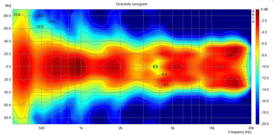
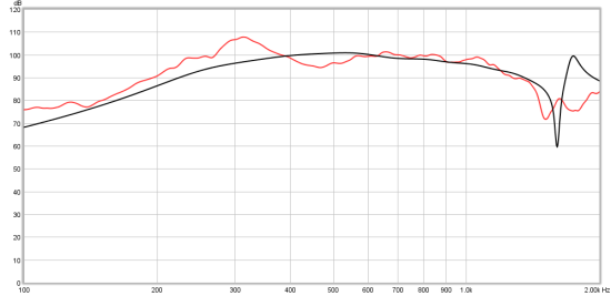
I did a quick test, placing the Celestion mid on S1:
Red Spade Audio: Celestion 4" mid test
comparing measurement vs simulation.
Also regarding the mids - as part of the group buy they will be offered at wholesale price.
Red Spade Audio: Celestion 4" mid test
comparing measurement vs simulation.
Also regarding the mids - as part of the group buy they will be offered at wholesale price.
Last edited:
Think about the wavelengths involved. Sound travels at 342M/S. At 1KHz (about as high as we are pushing these mids) you have a 342mm WL. Anything less than WL/4 is essentially irrelevant. If the driven surface of your cone is less than 85mm dia, the holes can be anywhere over that driven surface with little to no difference in output. An 8" driver driven to 1KHz needs a more central location for the port holes (Keep path length differences to below WL/4). I had no problems crossing a BMS 4550 at 900Hz to an 8" in a Unity I built. The BMS drivers buy you a bit of freedom at the bottom end of their range and work very well up high too. There are good reasons Tom uses these drivers in his commercial offerings.
I need to state up front that my grasp of phase isn't intuitive. IE, there are a lot of things in audio that I 'get' off the top of my head, but phase is one of those things that's quite bewildering.
But I was thinking about it this morning, and it occurred to me that the phase of the sound coming off of the midrange drivers won't change in any appreciable way as long as the dimensions of the chamber in front of the driver is smaller than one quarter wavelength.
Making standing waves - YouTube
For instance, if you excited the water in a swimming pool, no waves would form if you sealed off the top of the pool so that there wasn't enough room for the waves to begin. Once you do that, the water will continue to flow, but there will be no waves (because there isn't enough room.)
So preventing the waves from forming will keep the phase from rotating, and it's the difference in phase that creates the cancellation. (So minimizing that rotation should extend the response.)
Again, kinda thinking out loud here and trying to understand how we can extend the HF response.
I still think the diameter of the cone poses a problem; at one half wavelength we should see a dip around 1500hz. (Assuming a 4.5" cone.)
But tweaking the ports so that the pathlengths are reduced seems like it would buy us a few hundred hertz.
[/font]
G'day John
I had no problems crossing a BMS 4550 at 900Hz to an 8" in a Unity I built. The
Cheers
William Cowan
Maybe you should update your homepage?
") Great reading there. Have you finished the planar magnetics as well? In that case I would love to learn about it.
Great reading there. Have you finished the planar magnetics as well? In that case I would love to learn about it.Maybe you should update your homepage?
I know, I know. I have another webpage that gets more attention. I feel that a complete overhaul of my audio website is in order, but so far I haven't committed the time to it. Audio has taken something of a back seat for me lately. The planar system and the dual 8" Unity horns were my last two projects. I've been meaning to do some polar response plots for the horns before publishing the project, but other things like major house renovations (which I'm doing unassisted) seem to get in the way. Danielle, my lovely wife, probably has a bit to do with my choice of priorities too!
Someday.......
William Cowan
Last edited:
I need to state up front that my grasp of phase isn't intuitive. IE, there are a lot of things in audio that I 'get' off the top of my head, but phase is one of those things that's quite bewildering.
But I was thinking about it this morning, and it occurred to me that the phase of the sound coming off of the midrange drivers won't change in any appreciable way as long as the dimensions of the chamber in front of the driver is smaller than one quarter wavelength.
I still think the diameter of the cone poses a problem; at one half wavelength we should see a dip around 1500hz. (Assuming a 4.5" cone.)
But tweaking the ports so that the pathlengths are reduced seems like it would buy us a few hundred hertz.
Phase is tough for many, and you do need to get your head around the physical interactions that are taking place. Be aware that phase and frequency response are linked in linear devices. A change in the frequency domain will give a change in the phase behavior. If the phase behavior is good, the frequency response will also be good.
You are right that if the area under the cone is small, any resulting phase changes will be insignificant. That trapped air will start to look like a stiff spring, and combined with the slug of air in the port will create a low pass filter. If the spring is very stiff (small amount of trapped air) and / or the slug of air in the port is very light the the frequency of this filter will be pushed higher, further reducing the phase shift at a given frequency too. It is favorable not to push this too high, and to actually utilize this physical LPF to clean up some of the out of band distortion components coming off the cone and also to provide some of your crossover slope.
I successfully use 8" drivers crossed to a BMS 4550 at around 900Hz. The Unity horns I use in my main system are crossed only a little higher, I'm not sure why you want to cross at 1500Hz? The mid drivers have to be impractically close to the compression driver if the X/O is so high, or the notch from the reflection out of the apex of the horn will be in your passband. That little BMS (or the B&C DE25 in the main system) can handle everything an Australian Monitor 1K2 can throw at it, so surely driver protection is not your issue here? If your compression driver is too fragile, then perhaps you should buy the B&C or BMS to relax the constraints on your mids and simplify your design.
Speaking of crossovers, you will find that a well implemented unity type system will have a fairly simple crossover. I have found even a simple 1st order design with notch filters to correct response irregularities often works best. The nature of the CD horn means the compression driver has maximum attenuation at the bottom end of its response, reducing the load considerably. It's actually the top end of the compression drivers response that sets the sensitivity for the whole system. You will probably have to pad back the mid section a lot to allow the the compression driver to keep up. A decent driver will have no problems with a 900-1KHz crossover.
I should stop rambling.
William Cowan
- Home
- Loudspeakers
- Multi-Way
- Suitable midrange cone, for bandpass mid in Unity horn.