Since I couldn't get that Celestion 4", I went for the Misco RDC3T-A. It works damn well from what I've done with them so far. The best thing about them is that they were originally designed as a tweeter so once horn loaded they present a nearly resistive impedance. This makes it easier to use in a Synergy horn because you don't have to worry about its resonance screwing up the lower end frequency response. Its low end response is then purely controlled by the local area of expansion (i.e. local flare rate). I ordered a half case of them (30) and tested them all after breaking them in for 48 hours. Below are the overall average T/S parameters. The only way to come up with Vas was to use the sensitivity method with Smith & Larson Speaker Tester.

Fs = 1240Hz
Re = 7.76 ohms
Qes = 6.5631
Qms = 4.9345
Qts = 2.7557
Le = 0.4587 mH
Vas = 0.0559 L
Bl = 3.36
Cms = 3.36E-05
Rms = 0.77
Sd = 34.21 sq cm
After doing some more sims, I've *never* seen anything that performs like this driver on a horn. I'm trying to 'wrap my brain' around why this thing does so well.
On a flat baffle, this paper cone driver has a massive peak at 1500hz, which is clearly seen in the impedance plot. But put it on a horn, and it practically looks like a ribbon. No impedance bump at all. The impedance plot almost looks like a resistor! If anyone can clue me in to why it's behaving like this, please chime in! I've never seen behavior like this on a horn, and I can't figure out why it's doing this.
I'm guessing this has something to do with MMS? Tom says we want to size the horn throat to 'load down the driver's impedance curve.' In a horn that's one cubic foot, we have 33.6 grams of air. Four of our Pyle midranges have 15 grams of mass, while six of our cone tweeters have a mass of 1.5 grams. That's getting into ribbon territory - my ribbon has an mms that's one eighth of that.
I did some googling about "resistive loads" on horns, and came up with this discussion with Tom Danley. (Is it just me, or does it seems like there are only half a dozen people in the world that really grok this stuff?)
zmarchive.com psw-srf: 11560 Horn impedance effects
In a sealed or vented box, one has a resonant system (s) and the motion of the motor coil produces a back emf with reflects the reactive forces governing its motion. These would be mass and spring force and when the motor coil reflects them to electrical terminals, they appear to be capacitance and inductance.
Reactance’s allow the impedance to be higher because the current and voltage are not in phase.
When you sweep a sealed box, what you see is at DC, the Rdc, then higher in Frequency, you see the system is dominated by inductive reactance, higher up at resonance, it is a high impedance AND resistive (no reactance). Above resonance the impedance falls to its lowest point, Rmin. This is where the series inductance AND moving mass are equal but opposite reactance’s and cancel out, leaving another resistive point.
Above that, the impedance climbs as the series inductance of the coil dominates.
At resonance, the high impedance is set by the sum of the mechanical losses in parallel with the acoustic radiation (the important part). Unfortunately, that impedance appears to be very large and little power is delivered.
So here is the ideal horn, one takes a really strong motor driver, put it in a sealed box so that its resonance is somewhat above the desired low cutoff.
You size the motor strength to give you a really wide impedance curve, meaning the driver has available mobility and can be loaded down acoustically.
You have a proper horn, large enough to supply a constant (enough) load at the low cutoff.
For a 50% efficient horn, you size the driver area to throat area (compression ratio) to load down the drivers impedance curve until its about 2 times the Rdc. Over the band width this condition is achieved, the horn load is resistive and 2 times the Rdc.
Here, half the power is dissipated as heat from I^2 X Rdc loss, the other half is in the I^2 X Rad, resistive load the radiation puts on the drivers velocity.
In real life, few horns are 50% efficient but in any case to what ever extent the horn or cabinet design raises the system efficiency, it does so by adding this load, which shows up in series with the Rdc, raising the impedance.
Last edited:
What was the price of the Misco's in a 30 units batch?
They are $8.39 each for a half case (30 pieces). So, it was a little over $250 for them. If you buy a full case (60 pieces) the price drops to $6.44 each.
After doing some more sims, I've *never* seen anything that performs like this driver on a horn. I'm trying to 'wrap my brain' around why this thing does so well.
On a flat baffle, this paper cone driver has a massive peak at 1500hz, which is clearly seen in the impedance plot. But put it on a horn, and it practically looks like a ribbon. No impedance bump at all. The impedance plot almost looks like a resistor! If anyone can clue me in to why it's behaving like this, please chime in! I've never seen behavior like this on a horn, and I can't figure out why it's doing this.
I'm guessing this has something to do with MMS? Tom says we want to size the horn throat to 'load down the driver's impedance curve.' In a horn that's one cubic foot, we have 33.6 grams of air. Four of our Pyle midranges have 15 grams of mass, while six of our cone tweeters have a mass of 1.5 grams. That's getting into ribbon territory - my ribbon has an mms that's one eighth of that.
I'm glad somebody followed up on what I've been doing. Somehow I knew it would be John.
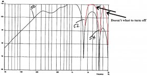
") Another bonus of the flat impedance is it eliminates the need for a Zobel network. Anything that removes parts is good in my book. The only problem I've been having is getting it to "turn off" after the 1/2 wave cancellation notch. The SPL wants to come back to the same level, so the normal first order crossover combined with the acoustical rolloff isn't enough. By adding more front chamber air volume helps, but it is a balancing act. Too much air volume and you get some ugly high frequency peaking. This is the area I'm currently working on. Once I get this figured out, I'll be much closer to finishing my horn. Still not ready for prime time.
Another bonus of the flat impedance is it eliminates the need for a Zobel network. Anything that removes parts is good in my book. The only problem I've been having is getting it to "turn off" after the 1/2 wave cancellation notch. The SPL wants to come back to the same level, so the normal first order crossover combined with the acoustical rolloff isn't enough. By adding more front chamber air volume helps, but it is a balancing act. Too much air volume and you get some ugly high frequency peaking. This is the area I'm currently working on. Once I get this figured out, I'll be much closer to finishing my horn. Still not ready for prime time.Attachments
Tom has already said that the acoustical pressure is much lower in the corners. This is why it is a good place to locate the mid ports. This in addition to having the crossover correct makes the mid ports pretty much acoustically invisible to the compression driver. A round horn is not the best solution for a Synergy/Unity horn.I'm glad this thread has kept things objective, because I'm afraid Paul's measurements seem to provide the 'smoking gun' in my hypothesis. (My hypothesis being "I think the Unity horn is square for a reason.")
Thank you JLH for sharing your knowledge and experience.
I think there are a way more people that are following and interested for the Unity and Synergy horns and your trial, then it seems.
If the SH-95 will be more affordable I'll buy it, but it' $4.000-$5.000, so I have no choice but try the DIY.
so, thank's again for your time and trial. .
Sergey
I think there are a way more people that are following and interested for the Unity and Synergy horns and your trial, then it seems.
If the SH-95 will be more affordable I'll buy it, but it' $4.000-$5.000, so I have no choice but try the DIY.
so, thank's again for your time and trial. .
Sergey
I'm glad somebody followed up on what I've been doing. Somehow I knew it would be John.
They are $8.39 each for a half case (30 pieces). So, it was a little over $250 for them. If you buy a full case (60 pieces) the price drops to $6.44 each.
Oh I am so in for a group buy!
Oh I am so in for a group buy!
On Friday I ordered a couple more candidates. One is a paper coned 4" tweeter from Goldwood, the other is the aluminum-domed 2" midrange from Dayton.
The 4" tweeter from Goldwood looks like it might be a drop-in for the Misco, similar to the situation that Paul found with the Pyle. (IE, not exactly the same, but close enough that it will work.)
The 2" will be trickier. Doug Kelley got me started on this Unity madness when he clued me in to one of his projects, which used the Dayton 2" at the throat of a Unity horn he built. Doug ended up buying Yorkvilles and has posted a few times in this thread.
But I've always thought the 2" would be a good candidate as a *midrange*, not a tweeter.
So I bought some of those on Friday too.
To use the Dayton will require some modding, as it specs aren't quite right. (Basically I intend to reduce it's back chamber, so it's FB and Q is much higher.) But it's combination of a powerful motor and a light cone may mean that it will be a better candidate than the W2-852SH from TB, which is still one of my favorite drivers for these projects.
Also, if you mess around with hornresp you might notice that some very odd drivers seem to work alright. For instance, the Goldwood has a ridiculous peak in it's response on a baffle, but drop it into a horn and the response looks great.
To be honest I am kind of reluctant because all the drivers seemingly working great in Unity are coming from weird brands such as Goldwood, Misco, Pyle, etc. It feels more comfortable knowing you have a Celestion inside or a Beyma or B&C, at least from a build quality point of view... I would like seeing more developed midrange drivers, with copper in their motors, etc.
Of course I am probably misjudging massively here, because as long as it's working it fits the bill but I guess you get my point.
Of course I am probably misjudging massively here, because as long as it's working it fits the bill but I guess you get my point.
If I wanted to use a woofer whos 2*Fs/Qes was more like 900 (BTW it works well below 400Hz), what would be the preferred way of bringing it down, or whould I just take what I can get and trim the rest in the crossover?
Can you explain your question a little better? What do you want to bring down - frequency, sensitivity, bandwidth, etc...?
To be honest I am kind of reluctant because all the drivers seemingly working great in Unity are coming from weird brands such as Goldwood, Misco, Pyle, etc. It feels more comfortable knowing you have a Celestion inside or a Beyma or B&C, at least from a build quality point of view... I would like seeing more developed midrange drivers, with copper in their motors, etc.
Of course I am probably misjudging massively here, because as long as it's working it fits the bill but I guess you get my point.
The original Unity used Misco 5" mids. The Sound Physics models also used Misco mids. A high priced mid is not required. The high performance and low distortion obtainable with these inexpensive mids is so great already, you would be entering the point of diminishing returns.
Can you explain your question a little better? What do you want to bring down - frequency, sensitivity, bandwidth, etc...?
Yes, I'm a little confused at the moment. When I wrote that post I was thinking of using mass to bring down the cone resonance. Anyway, here's what I'm trying to do.
I want to fit the 8PE21 to a unity. I want to find the right passband for it (one that comes naturally), and am willing to seal the baskets if required. That (with a volume of 800mL I estimate) will give a fb of 360Hz in free air. 2*Fs/Qes=875.
I want to go higher than 700Hz, pref 1kHz and will take up to 1k5Hz. I also want to go down below 200Hz so I can cross below the schroeder frequency and hopefully reduce some room reflections in the low midrange. Top end is more important although if the low end doesn't reach I'll need a woofer.
I'm now going to get on hornresp and run it up and down a horn trying to find its outer limits. Maybe you could save me falling in a hole?
For what it's worth, I was going to do a 60 x 60. PaulSpencer did a 60 x 60 and thought it was a little dry, but I think that's what I'm wanting. You suggested 60 x 40, maybe as I agree on the floor/ceiling. I'd also like pattern control down to at least 400Hz and so that will make it a little long.
Seems like one of the biggest challenges with the Unity is getting the mids to play high enough, or getting the tweeter to play low enough. If you look at the ones that John Sheerin built, and Paul built, and I built, you see this pattern over and over and over. Sheerin had a hard time getting 5" woofers to play high enough, and Paul is investigating using 4" midranges instead of 5" woofers.
The moral of this story?
Don't use an eight unless you *really* have a lot of time on your hands and a beefy compression driver that can be crossed low.
Or better yet, let's figure out how to combine compression drivers like Danley did, and then we can simply drop our xover point!
[/font]
The moral of this story?
Don't use an eight unless you *really* have a lot of time on your hands and a beefy compression driver that can be crossed low.
Or better yet, let's figure out how to combine compression drivers like Danley did, and then we can simply drop our xover point!
[/font]
Don't use an eight unless you *really* have a lot of time on your hands and a beefy compression driver that can be crossed low.
More like a 'beefy' 8" if Prof. Leach's math is to be believed as Allen's measured 8PE21 specs needs to be 'squeezed' with a ~69.835:1 CR to get a 150-1500 Hz BW.
GM
Seems like one of the biggest challenges with the Unity is getting the mids to play high enough, or getting the tweeter to play low enough.
Do you have an Aura Whisper on hand? Because its motor is a self-contained tube open at the top and the bottom, and the diaphragm fills up the whole top of the inner cavity, I bet you could raise its Fs considerably by snipping the bug screen and putting clay or something in the space under the diaphragm. (The "pole vent" of sorts, I guess.) I don't know of another driver where the total trapped volume under the diaphragm can be so easily reduced.
I wonder how that would work in Unity/Synergy.
Another thing way above my pay grade (but probably not yours...) is, I wonder how the Whisper would work as a CD. One could even turn them upside down s, and put a phase plug in the "pole vent."
Last edited:
Oops! In my haste I forgot to change the driver radius in my SS, so based on some specs you posted awhile back, which are different from what you just posted, it's 'only' ~17.76:1; still really high, though at a glance might make it viable for a HIFI/HT synergy concept where power requirements will be very low.
GM
GM
- Home
- Loudspeakers
- Multi-Way
- Suitable midrange cone, for bandpass mid in Unity horn.