I am curious about trying to add some single-ended bias to my BA-2 (as described in "Leaving class A"). I remember reading somewhere that it can be achieved by adding a resistor between the output and the negative rail but I can not find that post again.
I don't understand what you mean by single-ende bias. Please tell me more.
Do you want it to run as a single ended input or change the gain of the BA-2 front end?
Chris
No, it is neither about the input nor the gain.
In the article "Leaving class A" Nelson writes that it is possible to make a push-pull output stage being biased as a single ended class A stage for the first couple of watts. I am not very good at explaining so it may be more clear if you check the "Leaving Class A" article at passdiy.com.
In the article "Leaving class A" Nelson writes that it is possible to make a push-pull output stage being biased as a single ended class A stage for the first couple of watts. I am not very good at explaining so it may be more clear if you check the "Leaving Class A" article at passdiy.com.
Strange reading on front end pot P201
Dear all hi,
I am in the final steps before first power on.
I am measuring the P201 pot in order to set it at safe point (middle) and at one extreme i am getting 90 ohm ???
is this normal for a pot that is 5 kohm.
p/s
I am getting the same pot reading on both channels.
Please advice
Dear all hi,
I am in the final steps before first power on.
I am measuring the P201 pot in order to set it at safe point (middle) and at one extreme i am getting 90 ohm ???
is this normal for a pot that is 5 kohm.
p/s
I am getting the same pot reading on both channels.
Please advice
nikosgrgr,
I suspect that if you are measuring the pots after they have been soldered into the circuit then you will be also measuring the effect of the components connected to the pot.
I made the measurements before I installed the pots to avoid this.
Chris
Dear Backbones hi
I suspected that
Can i just trim them at 45 ohm and live them there (i do not want to get them of the PCB at this point)
What do you thing ?
Thanks
Dear Backbones hi
I suspected that
Can i just trim them at 45 ohm and live them there (i do not want to get them of the PCB at this point)
What do you thing ?
Thanks
I'm sure there is someone out there who can calculate whether 45ohms is correct but it is not me. I know de-soldering is awkward but a little time spent now may well save you time later. I did exactly what you have just done so we all learn from our mistakes.
Chris
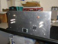
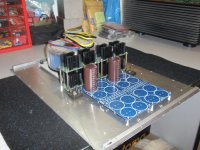
My implementation of BA-2
Dear all,
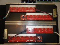
My version of BA-2.
Thanks to all the community for the valuable help-support and guidance.
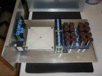
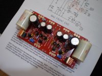
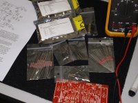
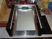
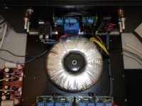
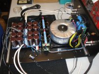
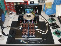
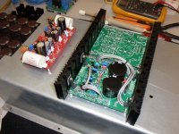
Below you can see photos beginning from the early construction stages till final ones.
Specifications:
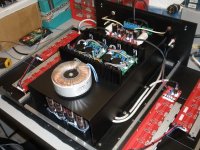
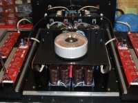
Power supply's
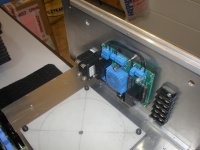
Front End separate regulated supply per channel.
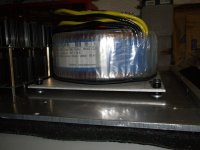
Output stage psu 1000VA transformer CRC philter topology high speed diodes bridges 120.000μf/63v per channel.
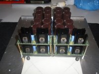
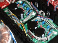
Output stage
Five pairs of output transistors per channel.
Typical measurements during initial tern on -burn in period & adjustment:
Right channel
DC of set 130mV Bias current set to 250mV after one hour of operation stable approximately to 270 mV I have a variance of approximately +/-10 mV on the source resistors between all 10 fet's
Left channel
DC of set 160mV Bias current set to 250mV after one hour of operation stable approximately to 270 mV I have a variance of approximately +/-40 mV on the source resistors between all 10 fet's in terms of current searing this channel don't measures as good as the right one (IRFP 240 Vgs 430-IRFP 9240 Vgs 397) i am open to ideas here can TL431 be the suspect? or the matching is not that close (having 40mV deference on two p type
mosfet's)


Dear all,
My version of BA-2.
Thanks to all the community for the valuable help-support and guidance.
Below you can see photos beginning from the early construction stages till final ones.
Specifications:
Power supply's
Front End separate regulated supply per channel.
Output stage psu 1000VA transformer CRC philter topology high speed diodes bridges 120.000μf/63v per channel.
Output stage
Five pairs of output transistors per channel.
Typical measurements during initial tern on -burn in period & adjustment:
Right channel
DC of set 130mV Bias current set to 250mV after one hour of operation stable approximately to 270 mV I have a variance of approximately +/-10 mV on the source resistors between all 10 fet's
Left channel
DC of set 160mV Bias current set to 250mV after one hour of operation stable approximately to 270 mV I have a variance of approximately +/-40 mV on the source resistors between all 10 fet's in terms of current searing this channel don't measures as good as the right one (IRFP 240 Vgs 430-IRFP 9240 Vgs 397) i am open to ideas here can TL431 be the suspect? or the matching is not that close (having 40mV deference on two p type
mosfet's)
you're still good if they are all in 40mV bracket ;
count on possible diff in resistor values
I will check and advice
Thanks
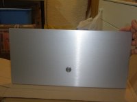
My implementation of BA-2
Additional photos
Additional photos
Attachments
-
 P6300677.JPG112.2 KB · Views: 96
 -
 P6300670.JPG76.1 KB · Views: 106
 -
 P6220656.JPG104.5 KB · Views: 133
 -
 P6220655.JPG106.7 KB · Views: 125
 -
 P6220654.JPG104 KB · Views: 145
 -
 P6090131.JPG140.7 KB · Views: 300
 -
 P6090126.JPG142.8 KB · Views: 323
 -
 P6040601.JPG106.6 KB · Views: 322
 -
 P6040596.JPG141 KB · Views: 326
 -
 P5300546.JPG110.3 KB · Views: 321
My implementation of BA-2
Additional photos 2
Additional photos 2
Attachments
Dear Backbones hi,Great looking piece of kit. I can't think I was getting such a range of values on the source resistors but I'm about to put in a voltage reg in mine so I'll measure them again. Zen Mod thinks it is OK so that's a good sign.
What does it sound like?
Still on measurement-evaluation / test stage.
I think that i will get there very soon.
Thanks for your kind words
Right channel
DC of set 130mV Bias current set to 250mV after one hour of operation stable approximately to 270 mV ]
I have just re-read your post. Do I read you have an output DC offset of 130mV?
If this is the case then perhaps this is too high. I asked on this thread what level of DC offset would be too high. The answer was anything over 20mV and in fact my amp is reading only 1 or 2mV at present. See here: http://www.diyaudio.com/forums/pass-labs/150653-burning-amplifier-ba-2-a-75.html
Best wishes,
Chris
Last edited:
Nikos how big are the heatsinks?
Dear Dufus,
3 pices of L=16cm x H=20 in total L=48 cm x H=20 cm per channel
- Home
- Amplifiers
- Pass Labs
- Burning Amplifier BA-2