I think that (apart distortion bandwidth and slewrate ) the main thing witch make the difference between preamps is their ability to drive very low impedance loads, something like 10 ohms.. Of course, power dissipation is not a concern.The most suitable for a pream to start is the SSA Headphones Amplifier from the post #1429. What do you think?
So it would be a very good idea to make a preamp from a headphone SSA.
Well, the lazy dogs will not forget they are many current feed back video operational integrated circuits witch can do it very well too.
what do you expect from your preamp: input/output impedance, gain, max. output level, etc.
The most suitable for a pream to start is the SSA Headphones Amplifier from the post #1429. What do you think?
How about lowering the supply rail. Then the cascoded VAS can be avoided and the more complementary bipolar can be used for the output stage (I don't think IRF610 with 20mA bias or even higher is suitable for preamp). EDIT: AND Salas type regulator will be more suitable for it too. The otput stage will look like the attached circuit (or you can "modify" the attached circuit with SSA frontend, doesn't matter)
Attachments
Last edited:
About SSA Preamp
I don't think that preamp has more benefit than drawback. DCB1 buffer is enough for me, but some MOSFET amps seem to need preamp. I think a SSA preamp will be suitable for SSA crescendo. The topology between the preamp and amp is also similar. I found that when the topology is similar between preamp and amp, the sound tends to be good.
I'm reluctant to build the SSA Crescendo because the supply rail is 70V minimal. I don't want to use a big trafo that I usually use for PA amp. I already consider using dual transformer, but what I have on hand are 2x30V=60V (below recommended value) or 2x42V=84V (too big even after regulation).
If I know how to modify the SSA Crescendo for 55-60V, I will sure build the preamp and the SSA Crescendo.
Yes it will be, as long as the VAS bias current is 20 mA or higher. Than of course you should take care of good heat dissipation from both VAS cascode transistors, especially because of this increased current level.
Regards, Andrej
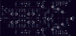
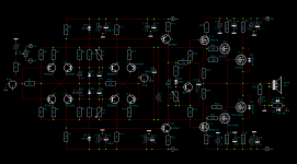
SSA Basic - Balanced - VAS + OPS - Mosfet ?,
LC, Please have a look at this sch, if eventually this should work, and if the termal stability would be an issue?
Thank You,

Attachments
SSA Basic - Balanced - VAS + OPS - Mosfet ?,
LC, Please have a look at this sch, if eventually this should work, and if the termal stability would be an issue?
Thank You,
Nice try, but this sch won't work at all. Corrections:
- omitt R17, R18, completely!
- T9, T10 must be at least 100V trannies like 2SA970/2SC2240, BC's would fail in the moment, VAS bias current max. 7 mA because of power dissipation on these BJT's
- you have complete mess around T13, T14, connected like this you'll have smoking hazard in a split second
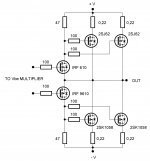
- so you want to drive outputs to the rail potential, correct output sch in attachment
- thermal stability won't be an issue as long as T11 is BD441 bolted to the main heatsink (needed to compensate positive tempco of IRF's)
Hope all this helps, regards, Andrej
P.S. OMG R10, R11 are not connected to the SSA bridge, only to LED !!!
Attachments
Last edited:
LC it's just too bad you swap from +/-60V and +/-50V rail to +/-76V and +/-63V rail as i follow BIGBT evolution in backround...
Marc
Please don't worry, I'll do all needed parts value calculations for lower rails potential, no problem.
")
I am on waiting NJL4281 since NJL4302 are arrived as NJL3281/NJL1302. I have 4x 22.000µF/40V, 2 toroids 300Va 2x25V, and some nice rubish heatsink that mesure l:150 x h:195 x d:27mm i think that wil be enough for one chanel ( 2 output transistor).Ooooo yeah Marc, cannot wait to hear the news from you, the board is just awesome. Please continue in a high gear mode, regards
Marc
Hi Marc
Drivers will be hot at operating conditions in either case. Faster getting there with more constant thermal conditions for the whole amp and the drivers themselves would be if they will have their own heatsink. Power dissipation is app. 1W per driver so you have to find suitable on board heatsink to hold the temperature of the drivers below 75°C in a closed amplifier case at max. musical loading programme.
Drivers will be hot at operating conditions in either case. Faster getting there with more constant thermal conditions for the whole amp and the drivers themselves would be if they will have their own heatsink. Power dissipation is app. 1W per driver so you have to find suitable on board heatsink to hold the temperature of the drivers below 75°C in a closed amplifier case at max. musical loading programme.
Hi Marc
Drivers will be hot at operating conditions in either case. Faster getting there with more constant thermal conditions for the whole amp and the drivers themselves would be if they will have their own heatsink. Power dissipation is app. 1W per driver so you have to find suitable on board heatsink to hold the temperature of the drivers below 75°C in a closed amplifier case at max. musical loading programme.
LC, if we admit t° in case is around 40°C i will need a heatsink with Rth = (75-40)/1W= 35°c/W per driver
I am rigth?
MArc
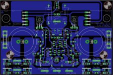
Just a little teaser 
The SSA BIGBT HP PCB is almost ready to be published. I will be the first one to build this version on a new shiny PCB which will be prepared by master Alex. Hardly wait to get a Christmas gift
The SSA BIGBT HP PCB is almost ready to be published. I will be the first one to build this version on a new shiny PCB which will be prepared by master Alex. Hardly wait to get a Christmas gift
Attachments
Last edited:
SSA - Bal. Lat-Mos
LC,
Thank You for the Sharp Eye Inspection, and all suggestions,
In a very early morning hours, tired eyes tend to sleep and errors appeared quickly. I did all the sugg. changes and hopefully now is the SCH correct, my I ask You is there any better currently obtainable Lat-Fets to successfully replace IRF 960-9610 fets to get same tempco as the OPs?
I upl. corrected SCH.
@ Jaj,
Please explain a bit more what do You mean by that and how to come closer to the rail Op. and not to raise OP DC40V Rails.
I have already all the PSU hardware for this particularly setup avail. and will try to replace the stock Amp. boards with these SSA-Bal. Mos.
Thank You, &
- so you want to drive outputs to the rail potential, correct output sch in attachment
- thermal stability won't be an issue as long as T11 is BD441 bolted to the main heatsink (needed to compensate positive tempco of IRF's)
Hope all this helps, regards, Andrej
P.S. OMG R10, R11 are not connected to the SSA bridge, only to LED !!!
LC,
Thank You for the Sharp Eye Inspection, and all suggestions,
In a very early morning hours, tired eyes tend to sleep and errors appeared quickly. I did all the sugg. changes and hopefully now is the SCH correct, my I ask You is there any better currently obtainable Lat-Fets to successfully replace IRF 960-9610 fets to get same tempco as the OPs?
I upl. corrected SCH.
@ Jaj,
Please explain a bit more what do You mean by that and how to come closer to the rail Op. and not to raise OP DC40V Rails.
I have already all the PSU hardware for this particularly setup avail. and will try to replace the stock Amp. boards with these SSA-Bal. Mos.
Thank You, &
Attachments
LC, you will get professional made boards?
Hi igor0203
Yes of course, maybe even GB if there will be some interest shown here.
@ Jaj,
Please explain a bit more what do You mean by that and how to come closer to the rail Op. and not to raise OP DC40V Rails.
I have already all the PSU hardware for this particularly setup avail. and will try to replace the stock Amp. boards with these SSA-Bal. Mos.
Thank You, &
I think you haven't fixed the output stage in your attachment.
No, I cannot help you with the technicality as I don't understand electronics (tho I guess you cannot do much). I'm just a builder (build-discard-build-discard-and so forth). And I'm pretty sure that the output topology suggested by LC will not give you a good sound.
I guess you want a higher wattage than the lateral circuit recently suggested/posted by Lazy Cat, which is very nice. How much power do you want btw? I know that low voltage transformer usually is low power also. But I think even if the voltage is low (40V) if you use a big power (current capability) transformer, 40V is fine (you just need to watch out the speaker impedance)
- Status
- This old topic is closed. If you want to reopen this topic, contact a moderator using the "Report Post" button.
- Home
- Amplifiers
- Solid State
- Simple Symetrical Amplifier