I still don't understand. There are two separate amps in one box with separate supplies each = dual mono.
no, yours are two similar amps
I meant two different amps, like in preamp/power amp
")
that is basicly what BA3 is
and especially when using seperated supply fore each
btw, genuine star ground means that every gound connection in the whole amp curcuit all meet in one and the same point, on the amp board
The first part is correct. "on the amp board" is irrelevant.... The single point is what matters, it's still a star ground if the single point is in the next room...
Roscoe

ok, one question regarding signal ground out from BA3 frontend to BA2 output board
do you really want to place it directly on BA2 power supply caps ?
or even worse, at bottom plate of box
but if its dedicated power supply ground connects directly to BA2 power supply ground, I guess you will have to, right ?
or wrong ?
but you can have one and only one ground connection, right ?
I would consider it very carefully
I still think the key is to look at signal level, and power/current draw
and place all ground connections accordingly to that
calling it star ground is simply rubbish, and wrong in my opinion
Yes. The whole point of the power supply caps is to minimize the noise between power and 'ground' so the cleanest ground will be the negative terminal of those caps.do you really want to place it directly on BA2 power supply caps ?
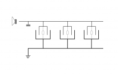
You do not want the chassis (box) to be the ground. Chassis should be connected to ground through a non-zero impedance, as shown in the schematics.or even worse, at bottom plate of box
The point of star ground is to minimize the potential of various "ground" references in a circuit. Every wire has impedance, and current is always being conducted towards ground, so as more impedance combines, the higher you get above ground. Chaining one ground to the next is a sure way to get further from ground, because each step adds mV. Star ground avoids this by having each ground connection go directly to the source, rather than chaining from some other ground that may have a voltage rise.calling it star ground is simply rubbish, and wrong in my opinion
I have no idea what you mean by rubbish; you're not being specific.
I have no idea what you mean by rubbish; you're not being specific.
before this I also said that there is no 'single star ground'
but that there can be multiple 'star ground' in a system
now after we have this debate I googled googled the subject star ground
and now even more convinced I am right about this
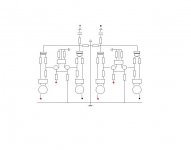
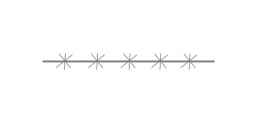
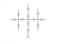
no matter how you do it, your 'star ground' scheme will look like this
if you consider the whole setup
the only choise you have left is what goes where
and that is basicly what we are arguing about
I have now found its called multipoint ground
Attachments
Are we taling about BA-3 or star ground
In my experience moving such topics to a separate thread can result in people missing important information.
If you look at Nelson's circuit diagram for the power supply you will see that the star ground is shown clearly. I have copied this layout (using a circuit board from Avondale Audio) so I have one ground connection from this star point going to the black speaker output connection and another to the BA-2 front end. This setup produces total silence.
Looking at the current setup with the voltage regulator I am now intending to connect the ground of this reg to the same star ground on the main power supply. Fortunately I have room on the power circuit board to solder this in place to the star ground but I can see for some they would not have the room to do this and therefore would need to have some form of staggered ground or multi-point ground. I think more importantly than putting all connections to the same point is that the connections along a multi-point ground are made good with minimum resistance. The ground wire which was connected to the front end of the BA-2 will now be connected to the ground of the BA-3. We shall see if this is successful when everthing is up and running.
Chris
Salas reg sounds interesting
I could 'steal' the reg/supply section from a couple of boards I have from symmetric B1 project GB
have thought about it, but I don't know if its suited fore this voltage
remember someone having pretty hot mosfets
and my trafo is 2x22Vac
maybe good heatsinks will do the trick
Check out the 'SSLV1.1 builds and fairytales' thread but I have now modified the reg and the mosfet are now running pleasantly warm and not terminally hot as before. The problem was that I was not balancing the input current and output current. The excess input current was resulting in excessive heat.
I'll keep you posted.
Chris
Also, don't higher value resistors introduce more noise relative to their lower rated counterparts?
yes
just got this crazy thought I would test it on my bass guitar
Before I realized BA2 front end was already obsoleted by BA3...
Nothing is obsolete. Just different.
ZM, You know where to get some Icar caps on this side of the pond? Or perhaps a known equivalent. considering this as last cap before BA output stage. I will have 54000 uF with seperate PSU case, another 24000uF power amp case. Haven't considerd whether there is anything to having the same amount in on each C leg of CRC
Last edited:
 ) GE were decent .....
- Home
- Amplifiers
- Pass Labs
- Burning Amp BA-3