Alastair is the Mosfet bias cap value critical i put in a 22uF ?
The gatestopper is now CF, have you had oscillation and choose CC for that reason ?
If you are refering to C3/C5 in schematic in post 353# anything from 1uF -100uF in post 347#...I have used 10uF 400V....The CC gate stop resistor I believe is because of inductive spiral of resistor element... I have used standard with no problems..
")
If I can locate a non inductive part I will use that when I do the mod!
Regards
M. Gregg
Last edited:
Good to hear M Gregg i have a what was in boxes aproach to component types.
Right now i´m having a battle to get small signals regs to fit.
+/- 150 regs is a hole other nightmare.
I have 10mm left in space between signal and power section.
I want a bigger box !!!!!
Try it without the +/- 150V regs...(unless you realy want them) Then again how will you know if its "better" if you have not heard it without? I think inrush protection something like CL60 and MOV back EMF protection is more imortant with these big toroids..
(you might get discrete components on tag strip in easier than the boards you made).LOL remember the discharge resistors!..
 Then again I guess you have resistors across the caps to balance the voltage and these would do the same thing!
Looking forward to the progress!
Regards
M. Gregg
Last edited:
On primary side i have softstarts.
I´m more worried about secondary side peakcurrent with so much F.
Can i have a peak at your +-150 schematic and what voltages do you get?
Still worried about enough voltage to drop for good filtration thats what made me think about regs.
I´m more worried about secondary side peakcurrent with so much F.
Can i have a peak at your +-150 schematic and what voltages do you get?
Still worried about enough voltage to drop for good filtration thats what made me think about regs.
On primary side i have softstarts.
I´m more worried about secondary side peakcurrent with so much F.
Can i have a peak at your +-150 schematic and what voltages do you get?
Still worried about enough voltage to drop for good filtration thats what made me think about regs.
I have used the same PSU as in the Tim Mellow amp, only using single caps in the rails..4700 across each of the 150V rails and 1000 across the +/-rail..There is a 1K 12W on the common rail between the caps and the Tx...(not between the caps and amp) to take the impact off the caps.. single bridge of UF soft recovery diodes..I am looking at electronic choke..however I will wait until the mods are complete before going further.
DC power rails;
Across both +/-……………………………..…334.3V DC
Minus rail…………………………………….-165V DC
Plus rail………………………………………+168.8V DC
The inrush suppressors help a lot!
I will send you my power measurements ...
Regards
M. Gregg
Last edited:
I have some IRFP450 regs built for the +/- 150 rails but wit only 15v to drop and as you say everything working nicely without i scrap it.
Your supplier is better than mine !!!!!!
I have some stepdown transformers thats about to be extensioncorded into the amp soon.
External PSU isn´t that highend, so 2 big 2000VA stepdowns on the floor must be Ultrahighend
Your supplier is better than mine !!!!!!
I have some stepdown transformers thats about to be extensioncorded into the amp soon.
External PSU isn´t that highend, so 2 big 2000VA stepdowns on the floor must be Ultrahighend
I have some IRFP450 regs built for the +/- 150 rails but wit only 15v to drop and as you say everything working nicely without i scrap it.
Your supplier is better than mine !!!!!!
Perhaps it’s coming by carrier pigeon and the power to weight ratio of the Tx Vs pigeon was calculated incorrectly….LOL
Perhaps a goose was higher power and its gone south for the winter...
I'm sure it will come soon..Which one did you order? The one with the shield and Oxy free copper windings?
Regards
M. Gregg
Last edited:
Irfp450 reg someone with the skills can perhaps sim it and optimize it.
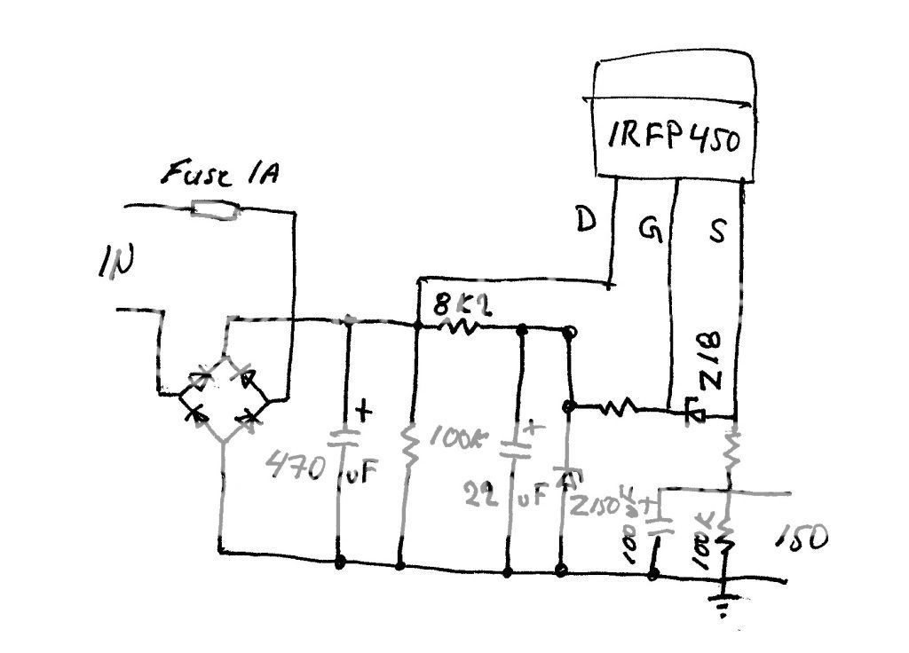
Diodes are BYT08
Missing value for gridstopper i used 1K
Resistor on output wirewound 5w 5,6R
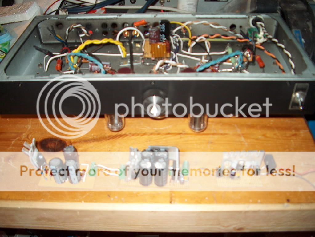
First cap is 2 pieces of 470uF in my breadboard.
A 0.1uF filmcap across output 100uF
Interesting,
Using Z18 to clamp the output...What is the short circuit current?
Also repeat short circuit survival rate of the FET?
You are in front with the mod.. I found I have no mica and washers for mounting the fet so ...I'm back to...the snail...
Regards
M. Gregg
Last edited:

I had uninvited guests at my house fridaynight.
So been busy cleaning and locking up the place.
They took an old car stereo and a chainsaw(what i´ve noticed so far) but cut every lock and damaged every door on garages and sheds.
Bought 8 cameras and are running cables and setting up a server for surveilance attached to cellphone.
My house was left alone but workshop is upside down.
OTL still here and in one piece but they took my 10+ years old laptop with measurement programs .
So been busy cleaning and locking up the place.
They took an old car stereo and a chainsaw(what i´ve noticed so far) but cut every lock and damaged every door on garages and sheds.
Bought 8 cameras and are running cables and setting up a server for surveilance attached to cellphone.
My house was left alone but workshop is upside down.
OTL still here
and in one piece but they took my 10+ years old laptop with measurement programs .I had uninvited guests at my house fridaynight.
So been busy cleaning and locking up the place.
They took an old car stereo and a chainsaw(what i´ve noticed so far) but cut every lock and damaged every door on garages and sheds.
Bought 8 cameras and are running cables and setting up a server for surveilance attached to cellphone.
My house was left alone but workshop is upside down.
OTL still here
Sorry to hear that..thats a real pig...what can I say it makes you so mad!!
Hopfully it will work out..insurance maybe?
Regards
M. Gregg
Sorry to hear that..thats a real pig...what can I say it makes you so mad!!
Hopfully it will work out..insurance maybe?
Regards
M. Gregg
Material stuff is one thing and can always be solved.
The main thing they stole is diesel fuel about 800 L that hurts in the wallet.
Right now biggest problem is that my wife is afraid to go out after dark, we live way out in nowhere and haven´t had any problems until now.
Insurance ?? Oh yes it´s that sign on the wall saying "Insurance by smith & wesson"
Or the nieghboorhood version "I shoot you dig we all deny"
4 cameras and 6 10W LED spotlights is up hope to get the rest up tomorrow and hopefully functioning before the weekend.
Back to topic.
Small signal regulator evaluation in progress.

For HV a IRF830 contraption has taken the lead over the IRFP450.
For heater a BYW29 and 1084 perhaps with the addition of a 8mH commoncore choke.
That poor 6V6 has been playing more music with the belly up then the right way
This is all probably way overkill.
Small signal regulator evaluation in progress.
For HV a IRF830 contraption has taken the lead over the IRFP450.
For heater a BYW29 and 1084 perhaps with the addition of a 8mH commoncore choke.
That poor 6V6 has been playing more music with the belly up then the right way
This is all probably way overkill.
If I may ask, what's the "latest" schematic (6v6?), if there is any.
Take a look a #353 there M Gregg put together the latest mods.
The 6V6 is my beat up testbed
Think i may finish the last on secondstage mosfet load tonight.
No toroid in sight
If I may ask, what's the "latest" schematic (6v6?), if there is any.
Post 353#
connect this to the 6c33c output stage grids..
Its still 220 Ohm cathode resistors split supply etc..
Regards
M. Gregg
- Status
- This old topic is closed. If you want to reopen this topic, contact a moderator using the "Report Post" button.
- Home
- Amplifiers
- Tubes / Valves
- Vacuum Tube OTL power amp!!