The whole unit can only draw 1.5 amps. The Dexa is capable of over .6 amps. I am using the Dexa in mine in place of the 7805 and do not have a problem but I am not using it to supply the 317 as well. Looking at the power supply schematic my concern would be where would you connect up. If you are trying to drive the shunt and RC filters this might be a problem with the DEXA 78xx. If not then you will have to lift a pin/cut a track on either u407 or u408. You could just purchase a Dexa 70907 to replace U407 which supplies the 317 with power and another Dexa 78XX for U404.
I have attached the power supply schematic in case you do not have one.
I have attached the power supply schematic in case you do not have one.
Attachments
i just looked again at the dacmagic's analogue stage schematic
is it possible to short the resistors R183, R191, R207, & R215 to obtain unity gain?
i intended to hit 1Vrms output voltage in my dacmagic, otherwise my gainclone might get distortion in full volume if i were to use the normal voltage gain (my gainclone has a gain of 22 and voltage swing of around 25V)
i'm thinking of changing the bypass opamp capacitor (C285, C284, C292, C291, and so on) to 0.1uF X7R capacitor as well. is it a good idea? i don't have any problem in soldering smd components
i attached the schematic below
View attachment DACMAGICAZUR analogue stage.pdf
Last edited:
Hi Deari just looked again at the dacmagic's analogue stage schematic
is it possible to short the resistors R183, R191, R207, & R215 to obtain unity gain?
i intended to hit 1Vrms output voltage in my dacmagic, otherwise my gainclone might get distortion in full volume if i were to use the normal voltage gain (my gainclone has a gain of 22 and voltage swing of around 25V)
i'm thinking of changing the bypass opamp capacitor (C285, C284, C292, C291, and so on) to 0.1uF X7R capacitor as well. is it a good idea? i don't have any problem in soldering smd components
i attached the schematic below
View attachment 243906
Is not possible to short the mentioned resistors ( this is not a gain stage...but a gig filter section , part of the virtual ground configuration how folks in Cambridge call it)
about the caps change : those are analog psu bypass...better are the originals plastic film that xr7 ( ceramic are ok for digital )
about gain problem : why not optimize the amp gain...? should be easer.
Ciao
Marco
Hi Dear
Is not possible to short the mentioned resistors ( this is not a gain stage...but a gig filter section , part of the virtual ground configuration how folks in Cambridge call it)
about the caps change : those are analog psu bypass...better are the originals plastic film that xr7 ( ceramic are ok for digital )
about gain problem : why not optimize the amp gain...? should be easer.
Ciao
Marco
thanks for the fast reply, Marco..
is it really sufficient for ne5532 to only have 47nf opamp bypass caps? in any amplifier i've ever built they all use 0.1uF in this position.
as for the gainclone, it's really not recommended to reduce the gain to half as it will interfere with the chip amp stability. hence i'm considering to lower the dacmagic output voltage
May we can add a 0.1uF MKT across ve+ and ve- ( pin 4 to pin 8 ) directly on the opamps.
A quite difficult mod because the little space...
I was planning to solder across the 47nF a 10/47uF .......but I did not because there are 1000uF very close .
the only way to reduce gain in your amp is by an attenuator made with 2 resistors before the input (the value depends of the amp impedance off course...) not very recommended all the way out....
cheers
marco
... I allso thought alot about the noisy MC34063 DC-DC converter. this one feeds the crystal, and most of the digital chips inside.
From the schematics the clock is fed from +5V_DIG, which is not clear whether it is (a) the +5_DIG from the analog power supply which also feeds the +5V_DAC or (b) the +5_DIG coming after the FB3 Ferrite Bead in the digital power supply just before U407/LDO Reg.
Assuming (b) is true and that U403/404/405 have already been replaced with Super Regs would there be any clock improvement by feeding the X1 24Mhz crystal from the +5_DIG of the Analog section ?
And the MC34063 is working with a switching frequency of maximum 100Khz... so there is a BIG chance that it is polluting the entire system - no matter how good filtration you use.
Assuming you isolate the clock X1(24Mhz) with its own power supply (flea clock approach), would U14/74VHC14 along with "noisy" 3.3V, be having any impact to the clock jitter ?
From the schematics the clock is fed from +5V_DIG, which is not clear whether it is (a) the +5_DIG from the analog power supply which also feeds the +5V_DAC or (b) the +5_DIG coming after the FB3 Ferrite Bead in the digital power supply just before U407/LDO Reg.
Assuming (b) is true and that U403/404/405 have already been replaced with Super Regs would there be any clock improvement by feeding the X1 24Mhz crystal from the +5_DIG of the Analog section ?
Assuming you isolate the clock X1(24Mhz) with its own power supply (flea clock approach), would U14/74VHC14 along with "noisy" 3.3V, be having any impact to the clock jitter ?
U405??? where?? I think you mean U402, U403 and U404
")
I've allready changed U404 - great stuff, these Dexa-thingy's
"B" is true. I have the service maual - so I know for sure
but I will start by giving it a new clock. i will post pictures when done.
About removing MC34063, and use Dexa instead. I will wait until I hear what kind of difference the clock will give.
I know that I't might be crowded with space inside the box. But with some creativity and willpower, things will work I'm sure
Wires should be able to be soldered directly to the pins of the LT317 or in place of the C89 and L2 which is no longer needed when a Dexa is used.
The Dexa's should be very stable, even without the big capacitors.
I'm just curious, what will happen with the "Unreg" and "Unreg2". it I pull the MC34063
I'm gonna power the clock from the 7815 (U402), since the clock draws very little power. The clock has a build on power supply, like the FLEA. And it also comes from Dexa. It cost only around 55$. He dosent have them on his website. Because people would' buy them, since they were to cheap.... but they should still be great. so I'm trying one
U405??? where?? I think you mean U402, U403 and U404
I've allready changed U404 - great stuff, these Dexa-thingy's
"B" is true. I have the service maual - so I know for sure
but I will start by giving it a new clock. i will post pictures when done.
About removing MC34063, and use Dexa instead. I will wait until I hear what kind of difference the clock will give.
I know that I't might be crowded with space inside the box. But with some creativity and willpower, things will work I'm sure
Wires should be able to be soldered directly to the pins of the LT317 or in place of the C89 and L2 which is no longer needed when a Dexa is used.
The Dexa's should be very stable, even without the big capacitors.
I'm just curious, what will happen with the "Unreg" and "Unreg2". it I pull the MC34063
I'm gonna power the clock from the 7815 (U402), since the clock draws very little power. The clock has a build on power supply, like the FLEA. And it also comes from Dexa. It cost only around 55$. He dosent have them on his website. Because people would' buy them, since they were to cheap.... but they should still be great. so I'm trying one
the dexa regulator sounds like a great stuff..but at 40 bucks a pop, i think i'll pass.
i'm still looking solution for cheaper version of dexa regulator (DIY, maybe?)
the dexa regulator sounds like a great stuff..but at 40 bucks a pop, i think i'll pass.
i'm still looking solution for cheaper version of dexa regulator (DIY, maybe?)
I know. but they are still half the price of, lets say - burson (75-85$)
Another thing. offcourse you can build your own. I'm just out of time for the moment. and my dac magic was really not giving the rest of my system credit. So thats why I choose Dexa. they give an simple and easy upgrade, that do not take much more space than the original 78xx. And at the same time compatible with the hole position/dimension for the original aluminium cooling plate - if any.
Try asking Matiasro, he seems to have a grip at things - especially the DIY regualtors:
http://www.diyaudio.com/forums/digital-line-level/142184-opening-new-dacmagic-21.html
If not then you will have to lift a pin/cut a track on either u407 or u408. You could just purchase a Dexa 70907 to replace U407 which supplies the 317 with power and another Dexa 78XX for U404.
Hi Ajcrock, assuming you have already replaced U404 with Dexa 78XX, would it be possible to power the X1 clock from U404's output which is the one also feeding the DACs ?
I am thinking whether this way I could get the flea clock benefits without the flea regulation circuitry.
It is not good to improvise in this sort of thing.Hi Ajcrock, assuming you have already replaced U404 with Dexa 78XX, would it be possible to power the X1 clock from U404's output which is the one also feeding the DACs ?
I am thinking whether this way I could get the flea clock benefits without the flea regulation circuitry.
The DAC`s chips regulator provide 5Vdc.
The oscillator has to deliver 3.3V RMS (24576hz), otherwise it would exploit the hex inverter 74vhc14.

Matias
It is not good to improvise in this sort of thing.
The DAC`s chips regulator provide 5Vdc.
The oscillator has to deliver 3.3V RMS (24576hz), otherwise it would exploit the hex inverter 74vhc14.
Matias
Precisely! That is also why I have bought a finished product from Dexa instead of building it myself. Dexa clock has a selectable output of both 3.3 and 5V. I know that I maybe should have changed the op-amp first. but I got the clock dirt cheap, and had to try it out
Not bad to be a fan of certain companies, as you are of Dexa.
Everything is on the level of DIYer you want to be.
Some people are happy to buy products and soldiers.
Some are happy to study the theory and nothing more.
Some to explore and build.
Some are artists.
Some are more extreme and some less ...
The important is that some less uV or a tiny ripple improvement is not substantial improvement. Also remember that many times is limited by the lack of improvement in another link in the chain.
I think at this level of mods, it's best as we arrived and no where.
Only, to reflect.
A hug.
Matias
Not bad to be a fan of certain companies, as you are of Dexa.
Everything is on the level of DIYer you want to be.
Some people are happy to buy products and soldiers.
Some are happy to study the theory and nothing more.
Some to explore and build.
Some are artists.
Some are more extreme and some less ...
The important is that some less uV or a tiny ripple improvement is not substantial improvement. Also remember that many times is limited by the lack of improvement in another link in the chain.
I think at this level of mods, it's best as we arrived and no where.
Only, to reflect.
A hug.
Matias
Spot on!
I would not call myself a fan of a company, after using just ONE of the products available from that partically company.But the dexa regulator, was costing half of belleson, burson, teddy and so on.
So I took a chance. And I think it worked for me. I believe that the upper frequencies are now alot more nice to listen to. And remember, my system is ALOT different than yours, as far as I can se at the pictures in your post. NOT being critical here! just saying that my system might, or might not, work well with the same mods as yours. Then I got this great offer, 55$ for an oscillator with build in powersupply. Most clock's I see around, cost' at least 250$. So I took a chance. Besides I live in Denmark. And we have to pay something ekstra, when buying things outside EU. So when getting good offers indside my own country's borders. It is alot easy'er to make and sweet deal and have fast and cheap shipping/service.
So there are many factors to look at.
But I agree 100% with you, that there is not much reason to buy or change anything, that will not make substantial difference to sound

I'll be back... maybe the clock is the key for me... who knows
100% agree, what I wrote basically it is because many times we lose the spirit of DIY (eg building a PCB) with promises that do not improve our team as much as we want.
To think, a few details: My DIY Regulators do not use sink (no need to match the screw hole in the sink).
Noise reduction as Texas is close to the Dexa, Burson, and so on.
Often the business war generates an arms race. Then 3 picoseconds, pristine treble becomes shrill versus your competitor. For us, it is important to know that precision instruments, 3 picoseconds are almost impossible to measure.
I hope you get the idea and reflect.
We hope the photos of your work.
A hug.
It is not good to improvise in this sort of thing.
The DAC`s chips regulator provide 5Vdc.
The oscillator has to deliver 3.3V RMS (24576hz), otherwise it would exploit the hex inverter 74vhc14
Would it be possible to improve the digital PSU by introducing a gyrator circuit after U12 (MC34063) ?
If not, what other options you would consider to reduce the switching noise from U12 on to the digital power supply ?
For powering X1 quartz crystal, even a simple cap multiplier with 2 transistors will be a great improvement over stock power supply.
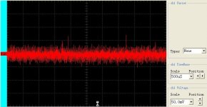
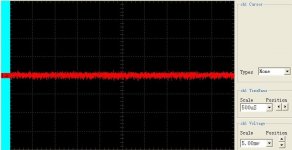
Ferrite bead FB5 should be removed and new 5V power supply (only for quartz crystal) connected to X1. Most important thing for this new power supply is low noise. Low noise at 1 Mhz is not important, important is low 1/f noise.
Capacitor C32 can stay and a bigger elcap (47uF or 100uF) must be added. And a smaller cap (SMD, 10nF, size 0603) is a must.
Improvement is measurable with scope and improvement is also audible. More details, more 3D sound.
Happy modding
Look at the Scale (lower right corner) on pictures. Both measurements taken at X1 power supply pins, before and after.
Attachments
Your question is very intelligent.
Is common paradigm that digital stage does not affect the final quality of the audio signal, but from my experience this is not true.
I do not know which will improve the incidence of U12 with a gyrator like that.
For sure we should measure the output of both regulators and estimate what is the change in the digital stage.
For an amateur I find it quite complex. We should resort to trial and error and place to listen for changes.
Also I think the change would be negligible.
For someone who does not change capacitors, clock power, regulators and audio DAC, or opamps seems to me nonsense.
A hug.
Matias
- Home
- Source & Line
- Digital Line Level
- Opening the new DacMagic????