Member
Joined 2009
Paid Member
Ok I am probably limited not to say stupid but wont to try out building this amp SSA BIGBT, just few questions before start
1. Bias is set by 1 K Trimmer, and at first powering on it must be on max resistance?
2. 2K trimmer is for dc offset?
3. the gain is how many , and can it be changed changing what resistors?
4. Thanks all for providing help to me I appreciate it!
1. Bias is set by 1 K Trimmer, and at first powering on it must be on max resistance?
2. 2K trimmer is for dc offset?
3. the gain is how many , and can it be changed changing what resistors?
4. Thanks all for providing help to me I appreciate it!
Strange to see a C comp in a current feedback loop.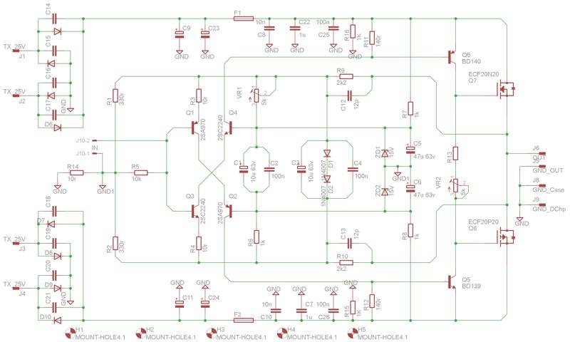
Marc
Yes, one of the advantages, with current feedback amps and well designed stages is you don't need any Miller compensation on the feedback loop witch reduce bandwitch and slew rates, and turn the phase from their best.are you talking C12-C13... they are there to reduce amplification at app 10MHz....and thus prevent oscillation..
there should should be some resistors in the R-C snubbers over the diodes..
Some serial R in the gates of Q7/Q8 ?in simulation.. there is a resonace peak off 8-10 db at app 10 MHz....
The amplifier feed-back loop is low impedance and pretty immune to RF and completely stable but the cap was purely in anticipation for RF pick-up from very long speaker leads and difficult load, it is not Miller compensation it is purely a filter.
This amplifier is capable to operate in VHF band depending on the transistors you choose.
Nico
This amplifier is capable to operate in VHF band depending on the transistors you choose.
Nico
Some serial R in the gates of Q7/Q8 ?
You can use gate stoppers if you please or if you have long tracks to the gates, but the amp did not miss behave without them in my layout.
Nico
P.S. I am as pleased with the performance as I was in the first instance when I made it.
I hope so ;-)The amplifier feed-back loop is low impedance and pretty immune to RF and completely stable but the cap was purely in anticipation for RF pick-up from very long speaker leads and difficult load, it is not Miller compensation it is purely a filter.
This amplifier is capable to operate in VHF band depending on the transistors you choose.
Better use some µH at the output than reintroduce RF in the feedback loop with the IM it can create ?
With my own current feedback Amp, i use shielded loudspeakers wires because of that, and grounded chassis on loudspeakers as well. With an audible improvement. (It is not a "magic cable" effect ;-)
PS: I used to show on tv a vhf signal across my amp to demonstrate the bandwidth of it. Very funny. A very heavy video distributor.
Last edited:
BTW, Nico, first, congratulation for this nice work.
Did-you plan to resume the different versions together in a post or a web site (i can help you on that), with measurements on each ?
According to the clever remarks of destroyer X, did-you plan to design a "Not so simple C.F. Amp from this idea, in order to promote Current feedback with 'nice looking' distortion numbers ?
Current feedbacks amps are so wonderful, so good to listen, and, in the same time quasi unknown, impossible to find as kits, that they, for sure, need some promotion.
Hi Esperado
The praise should go to Lazy Cat, I merely contributed a small portion. I suggested a thread with each design complete with schematics simulation PCB layout and measurements, BOMs, etc. but it never took off.
To be honest my interest in the thread was that the design was just so refreshingly different that I was compelled to add my preferred output devices, the lateral mosfets.
Kindest regards
Nico
Oh, sorry Nico, i was thinking at Lazy Cat, indeed, for those congratulations and questions. (age is a nightmare). I want to congratulate Idefix too for those wonderful board designs in this thread.
May i have your feeling about lateral mosfets ?
I explain, i had stopped electronic since 20 years, now, and i have no experience with some new products like those. My amp use IGBTs. I know Lateral have an advantage with the negative temperature figure, and it is a geat advantage to get rid off thermal compensation, but how did they sound compared with IGBT or HEX ?
And an other question, out of topic. I do not have any spice simulation experience, neither the softwares. Is-it a long run to learn ? I run an other very good old IGBT's amp, that i would like to modify from voltage to Current Feedback. It would be a way to do-it snappy without taking the risk of burning everithing with oscillation problems ? Just changing the CR path according to the nice idea of Lazy cat ?
Last edited:
Not an effect of age, i was always unable to remember any name i can't correlate with a face: Apologizes to Alex.BTW I think you are getting old Alex designed most of the PCBs here, I think.
But i can recognize a 3055 when it burn with it smell ;-)
BTW I think you are getting old Alex designed most of the PCBs here, I think.
Nico
Yes, the whole work is Alexmm duty, i just modify to adapt my own request instead of asking Alexmm to modify.
Marc
Member
Joined 2009
Paid Member
Looking at my heatsink and the need for 3 channels I don't think I can use any of the really nice pcb designs so far.
I'm going to start playing with a pcb design of my own, which like Hugh's Fetzilla pcb will mount flat onto the heatsink with the power devices sandwiched between the pcb and face of the heatsink.
I don't need gobs of power (+/- 36V rails for power devices to yield 55W rms into 8 Ohm) so 3 channels on one heatsink will be OK and I only need 1 pair of output power devices. Power supply will be strictly separate.
Anyhow, seeing as I'm the 'champion' for an all-BJT version (????) I'll report back if it looks like this is going to work. I need it built in the next few weeks because my HT system will be off-line without it !
Last edited:
Gareth,
I can recommend the FetZilla mounting style. It saves space, confers very good cooling, and simultaneously mounts the pcb along with the output devices saving brackets, standoffs, and other messy options. And if you incorporate the power supplies too, you can minimise power supply lead inductance and make it easier to get going.
I really like Andrej's complementary approach here, it sims extremely well with almost an evenly descending train of artefacts. My only concern is that you invariably need to set up tight balance between upper and lower halves with consequences for offset control, but aside from that, his approach to avoid AC coupling is inspired and innovative.
Cheers,
Hugh
- Status
- This old topic is closed. If you want to reopen this topic, contact a moderator using the "Report Post" button.
- Home
- Amplifiers
- Solid State
- Simple Symetrical Amplifier