to lineup,
was the 100w into 8ohms load [post#9] your final take on the Fetzilla design? I'm begining to have an interest...
abeeter
I am afraid there is no final schematic.
There are different schematics evolving.
And changing a bit depending on who.
If you follow the discussion you will find several options that will work.
As you can see from posts:
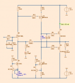
Post #1130 on page 113 shows the last schematic.
----
I will leave posting of the final schematic to Greg. It's the AC coupled version, and uses 2SK170BL as input device and ZVP3310A as the voltage amplifier
Hugh...will you post the schematic.....I can see caps added at the output devices.. as well as the phase lead....
Mike,
How's the sound? Inquiring minds yada yada.......
Hugh
I had an incident . . . . bad connection VAS resistor

need to change some transistors
It sounded OK before it blew but that was through VERY poor speakers with a cheap netbook as a source. Even when I have two working amps, until my stuff arrives, my source will be the headphone socket of a macbook - which is actually pretty good - and Quad 11L speakers.
This is an unfamiliar system and I will have nothing to compare the amp with so I'm not sure how much I will be able to deduce about the sound of the amp, but of course I'll get some kind of an idea.
Anyway, Over & out for now - I'll tell you when they're working, but don't hold your breath.
mike
I post here the latest version of Fetzilla
that I would recommend for those who want to build.
This version should be stable and uses IRF9610 for VAS.
There are other versions, too,
if you search thread backwards
or ask swordfishy, mikelm and AKSA.
that I would recommend for those who want to build.
This version should be stable and uses IRF9610 for VAS.
There are other versions, too,
if you search thread backwards
or ask swordfishy, mikelm and AKSA.
Attachments
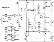
Q2's role is gravy, not the main dish.what is the role of Q2?
M3 is VAS, Q1 is sliding bias, D1-D2 are square law currents
into the load, R1 is always on bypass current across the load.
Q3 was never VAS, merely a unity voltage gain current booster.
When collector Q3 is connected as bootstrapped phase splitter,
both M3 and M2 become VAS. Current in Q1 reduced slightly to
becomes more like current in Q3, if that side-effect matters.
I don't suggest the dumbed down version of circuit you should
be ignoring anyway. Without all the gravy, this circuit rings...
Either way, something still needs done about offset.
Attachments
Last edited:
should Q2..not be attached to the upper mossfet drive..?? and then act like a bias spreader..controlled by the diodes to prevent the fet from turning off...
That would be PFB, locks the whole thing to one rail.
MOSFETs here are identical twins, not compliments...
Bias already spread by Q1. No MOSFETs ever turn off.
Would require a current mirror at the top rail to do as
you suggest. Might reduce 2nd harmonic distortion.
Or perhaps more gravy that does nothing critical?
Last edited:
1st comments on my DC linked version
well, I listened to music today - just one channel.
After I had an incident yesterday I thought I might have damaged a transistor but I think actually they were all OK.
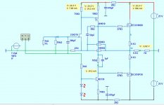
What made me suspect that something was wrong was was a hum that I hadn't noticed before and I suspected a problem - but after changing all trannies ( except the VAS MF ) I concluded that the hum was normal and later in spice I found that this cct does not have good PSRR.
What did reduce the hum was was adding 20R + 470uF between the o/p stage & the VAS I intially did this in the pos rail but subsequent spice testing showed very big gains are seen from having these filters in both rails.
This will not only reduce the 100 hz hum but also drastically reduce other PSU noise. In the region of 1K - 20khz we see an improvement in PSRR between 35 & 55dB !
This will have a seriously good effect on sound quality.
So I would recommend that anyone building this should incorporate this line filter.
Too soon to assess sound in general other than to say it sounds promising
cheers
mike
well, I listened to music today - just one channel.
After I had an incident yesterday I thought I might have damaged a transistor but I think actually they were all OK.
What made me suspect that something was wrong was was a hum that I hadn't noticed before and I suspected a problem - but after changing all trannies ( except the VAS MF ) I concluded that the hum was normal and later in spice I found that this cct does not have good PSRR.
What did reduce the hum was was adding 20R + 470uF between the o/p stage & the VAS I intially did this in the pos rail but subsequent spice testing showed very big gains are seen from having these filters in both rails.
This will not only reduce the 100 hz hum but also drastically reduce other PSU noise. In the region of 1K - 20khz we see an improvement in PSRR between 35 & 55dB !
This will have a seriously good effect on sound quality.
So I would recommend that anyone building this should incorporate this line filter.
Too soon to assess sound in general other than to say it sounds promising
cheers
mike
Last edited:
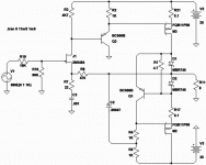
Mike....
I always make split supply....one for the frontend with voltage-doubler and then rippled down trough three or four RC.-groups..then the front end starts slowly and is dead quiret and not modulated from the main rails..The main supply is crude and big...like 4x27mF...this is class A-B and needs a large current dynamic headroom to perform well
the TO126.. will easily handle 0.5 W
Last edited:
I recon you already use some bigger electrolytic caps close the output stage.
Yes - at present I have 1000uF next to the rectifier diodes, 10,000uF next to the boards and 1000uF on the boards for the o/p stage.
Hi Hugh,
I don't understand your findings.
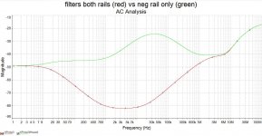
In spice I added 0.5V AC to each rail - this was the only AC source. I then ran an AC analysis - here are the results.
When I added the neg filter to the pos one I thought it sounded better but it was late, with one speaker only so I would not swear by my findings - I will try removing the pos when listening conditions are more favourable . . . . but the spice graphs tell a powerful story:
mike
I don't understand your findings.
In spice I added 0.5V AC to each rail - this was the only AC source. I then ran an AC analysis - here are the results.
When I added the neg filter to the pos one I thought it sounded better but it was late, with one speaker only so I would not swear by my findings - I will try removing the pos when listening conditions are more favourable . . . . but the spice graphs tell a powerful story:
mike
Attachments
I post here the latest version of Fetzilla
that I would recommend for those who want to build.
This version should be stable and uses IRF9610 for VAS.
There are other versions, too,
if you search thread backwards
or ask swordfishy, mikelm and AKSA.
lineup, thank you!
and yes I saw the version of danspy I might as well have a look at it...cause it was built and tested
Great mikelm. Good suggestion. I like getting a good performance increase with just a few passive devices.
Going to add your suggestion to my design even though there's no noticeable hum with the capacitor coupled version....at least with my 89dB speakers.
Great to hear that the sound has potential. Hope you will try the capacitor coupled version one day though.
Going to add your suggestion to my design even though there's no noticeable hum with the capacitor coupled version....at least with my 89dB speakers.
Great to hear that the sound has potential. Hope you will try the capacitor coupled version one day though.
- Status
- This old topic is closed. If you want to reopen this topic, contact a moderator using the "Report Post" button.
- Home
- Amplifiers
- Solid State
- JFET input, MOSFET VAS, LATERAL output = Perfect!!