Fantastic. Thanks Scottmoose.
The other question is tuning- I read somewhere that you should tune the quarter wave length around 5 khz away from driver resonance..the prob is I can't remember if that is above or below the driver resonance! Mind you I doubt its easy to get it spot on anyway, too many factors involved..
The other question is tuning- I read somewhere that you should tune the quarter wave length around 5 khz away from driver resonance..the prob is I can't remember if that is above or below the driver resonance! Mind you I doubt its easy to get it spot on anyway, too many factors involved..
There are no 'shoulds' in terms of Fp, though it's generally inadvisible to tune below 0.707 Fs. Martin's Alignment tables assume tuning to Fs for e.g., but there are a wide variety of alignments (technically infinite, although that doesn't mean they're any use) depending on what is desired.
.........or take the quite high qts into consideration?
I do. Good rule-of-thumb in today's T/S centric 'society':
Up to a ~0.707 Qts after any series resistance is accounted for: sim a T/S max flat alignment and make Fp whatever Fb it calcs.
Above this point, it's generally better to use Fp = Fs/Qts and definitely if it's a >1.0 Qts or you want the TL equivalent of a T/S max flat [AKA max flat impedance] alignment.
Works for me anyway.
") Try it both ways plus ignoring Qts, calculate them using MJK's Classic Alignment Tables, sim them in his software and let us know what you think.
Try it both ways plus ignoring Qts, calculate them using MJK's Classic Alignment Tables, sim them in his software and let us know what you think.GM
Put the driver between S1 and S2 , in "driver-arrangement"".
Hmm, you sure about this? My understanding is that the driver is centered at S2.
GM
This is a sketch of the design. The rear chamber is effectively 1/3 of the line with the 'fins' or wings having a folded line inside exiting at the rear. The line is about 4.5 ft long. It's symmetrical but the lower part is extended down to the stand.
View attachment img043 (1).zip
sorry, the image doesnt seem to be showing for some reason.
View attachment img043 (1).zip
sorry, the image doesnt seem to be showing for some reason.
Last edited:

Looks like some stylized '50s era Cadillac tail fin/light assembly.
GM
....Is this a half-wave TL or an quarter-wave with the terminating openingmarked yellow in this picture copy?
Attachments
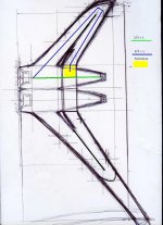
marked yellow in this picture copy?
My sketch wasnt great but you got it exactly (1/4)- I made a small model last year but I couldnt figure out the internals until now

Will it work in theory? I'm worried about lobing..
Last edited:
..Will it work in theory? I'm worried about lobing..
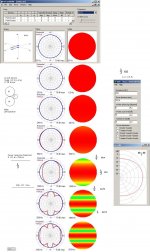
I have no doubt that this wouldn't work but the lobing issue is another consideration to deal with:
I would at first hand add another smaller FR driver to cure this inevitable problem or place a small capacitor in parallel with the lower placed driver if and only if the drivers are hooked up in series.
b
Attachments
I have no doubt that this wouldn't work but the lobing issue is another consideration to deal with:
I would at first hand add another smaller FR driver to cure this inevitable problem or place a small capacitor in parallel with the lower placed driver if and only if the drivers are hooked up in series.
b
Thanks Bjorno
No doubt it would or wouldnt work? would, I hope!
I thought about adding a tweet and or maybe a 3rd sealed driver enclosure and rolling the Hfs off the outside two.. but maybe its a bit overkill, looks wise.
I like the idea of rolling off the lower driver but don't I need an inductor?
how does that work?Hi Bill,
Sorry for being late...
It will work
Good idea.
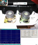
Place a small capacitor in parallel with the lower placed driver if the drivers are hooked up in series but when using the drivers in parallel: You're right: An inductor would be the first to choose.
Example of capacitor use: The patented Logitec Fdd2 filter : See the submitted picture
b
Sorry for being late...
No doubt it would or wouldnt work? would, I hope!
It will work
I thought about adding a tweet and or maybe a 3rd sealed driver enclosure and rolling the Hfs off the outside two.. but maybe its a bit overkill, looks wise.
Good idea.
I like the idea of rolling off the lower driver but don't I need an inductor?
Place a small capacitor in parallel with the lower placed driver if the drivers are hooked up in series but when using the drivers in parallel: You're right: An inductor would be the first to choose.
Example of capacitor use: The patented Logitec Fdd2 filter : See the submitted picture
b
Attachments
Place a small capacitor in parallel with the lower placed driver if the drivers are hooked up in series but when using the drivers in parallel: You're right: An inductor would be the first to choose.
Example of capacitor use: The patented Logitec Fdd2 filter : See the submitted picture
b
Cheers dude! Tack sa mycket!
Ah, so Logitec figured out a way of not using an inductor and.. strictly speaking ..
I could try this but not for commercial use.I will probably go this route or I had an idea to put an omni type lens in front of one driver.
- Status
- This old topic is closed. If you want to reopen this topic, contact a moderator using the "Report Post" button.
- Home
- Loudspeakers
- Full Range
- placing the driver 1/3rd of the length down a TL