Hello,
I'm almost ready to start soldering. Just waiting for fets from Spencer and a few more things missing... Mostly, I've followed Salas BOM. So, no exotic parts in case I some of them decide to go up in smoke.
So back to the things missing... Solder, RCA's and internal wire (+ power inlet socket?)
Many too choose from, too many opinions to get follow.
What should I look in for while looking for these parts? As you might guessed, this is my first project.
Regards, Tomas.
Buy solder that has lead in it.
The lead free are generally more difficult to use by beginners and experienced.
Buy Eutectic solder.
63/37 is generally available and is usually the cheapest.
Don't buy 60/40, this has a pasty range and suffers bad joints if moved during cooling down through the pasty temperature range.
Try to achieve a mechanical joint before soldering.
loop two wires at the junction around each other, or twist them around each other, or fill the PCB hole with a lead that just fits.
Make sure your PCB and the components leads are clean.
Don't inhale the soldering fumes.
Tin your tip with a thin even coat of solder before starting.
Repeatedly (once for every joint) "clean" your tip with a quick wipe across a damp sponge.
Internal Mains wiring.
Try to double insulate both the cable and the connections. As a DIYer you are likely to want to check/test/measure with the lid off while powered up. We want to keep you as a member.
Last edited:
Andrew, that is a good reminder list with recommendations. Thank you.
Alright, so I'm wiping off my consideration all Cu, Ag, Au additives in a solder, whatever conductivity they promise.
As for wires... Solidcore? Multicore? Insulated (of course!) manually (making an air gap dielectric) or doesn't all that matter? Gauge? Same for signal, as for mains? An example of double insulation won't go amiss.
Rca's...
Regards, Tomas.
Last edited:
Mains cables come in 2core or 3core versions.
Each core has it's own colour coded insulation.
All the insulated cores are then insulated with a common outer cover.
Retain this outer cover.
At the ends the core insulation will be exposed. The wires will be exposed.
Wrap some insulation around the wire and it's terminal.
This provides a minimum single insulation for all your mains wiring., But it is still vulnerable to damage, to insulation unwrapping, joints falling apart.
Wrap a second insulation layer or glove/sleeve around the single insulated wires and terminals. If this is a tight fitting sleeve then an additional mechanical fixture can be dispensed with. Do not rely on adhesive that you have not tested for temperature extremes and for effective lifetime to hold insulation in place.
Now all mains should be double insulated and should not fall off even if the adhesive fails nor if the joint breaks.
A really tight ti-rap can make an effective mechanical fixing to prevent insulation unwrapping or sliding off/
Commercial gear with a warning label on the outside "do not enter" will generally not be to this standard.
Double insulated equipment will be to at least this standard and probably much safer than our amateurish attempts at protecting ourselves.
Last edited:
Mains double insulation. Full. Tight. Snug. Check. But What is "ti-rap"?
And what about signal wires? Same rules?
I think Andrew means cable ties.He will no doubt correct me if I'm wrong.
Thanks. Marra, what signal wires have you used?
I'm using Kimber TCSS
yes, these small changes are not critical to operation.I don't want to be annoying with those questions but could I put 200k or 240k instead of 220k? 910k instead of 1M? Thanks.
Another DCB1 is born!
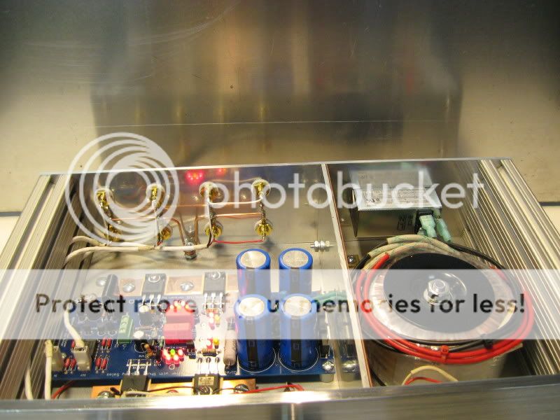

I can't comment too much on the component choices, I did not populate the board. The preamp is powered by an Antek AS-1215, 16v secondaries. Shunt voltages are -9.71v. and +9.65v.. The Fairchild MOSFETs run extremely cool with no load. I will put a signal through it,tommorw to see how all performs. If it is anything like the original Hypnotize or the original B1, I think another winner is present. Thank you, Salas!
I can't comment too much on the component choices, I did not populate the board. The preamp is powered by an Antek AS-1215, 16v secondaries. Shunt voltages are -9.71v. and +9.65v.. The Fairchild MOSFETs run extremely cool with no load. I will put a signal through it,tommorw to see how all performs. If it is anything like the original Hypnotize or the original B1, I think another winner is present. Thank you, Salas!
Nice construction. Check also the voltages across the fat resistors (10 Ohm?) next to the blue filter caps to be something around 1.5-2.5V, and the DC offset on audio outputs to be in the very low mV. Then you can safely hook it up and let us know how you liked it. After 48 hours play it will mellow out a bit also.
greetings all,
got my boards and various parts to start populating. read the posts and now, of course I have a couple of questions.
1) I'm going to feed a ta2020 amp with no input caps. some docs mention not to feed it dc. So I read in this thread to put output caps with a bypass cap. Is this true and if so, I read 1.5 uF and .0047 uF bypass. Are those values OK or is it a question of taste.
2) I tried to test the delay circuit on a breadboard using the pew tq2 relay (I think its an amorat or something like that) . I here the coil engage when I put 12V but the circuit does not delay. I measure the 550 center pin and V increases to about 4V so the timing cap and resistor seem to wotk fine. tried changing the 517 and still no turn-on delay. Any clues?
what is the turn on delay period?2) I tried to test the delay circuit on a breadboard.............. I here the coil engage when I put 12V but the circuit does not delay. I measure the 550 center pin and V increases to about 4V so the timing cap and resistor seem to work fine.
If it is very short you won't be aware of it.
- Home
- Source & Line
- Analog Line Level
- Salas hotrodded blue DCB1 build