Hello Rakesh, as Hugh says, good work, however......
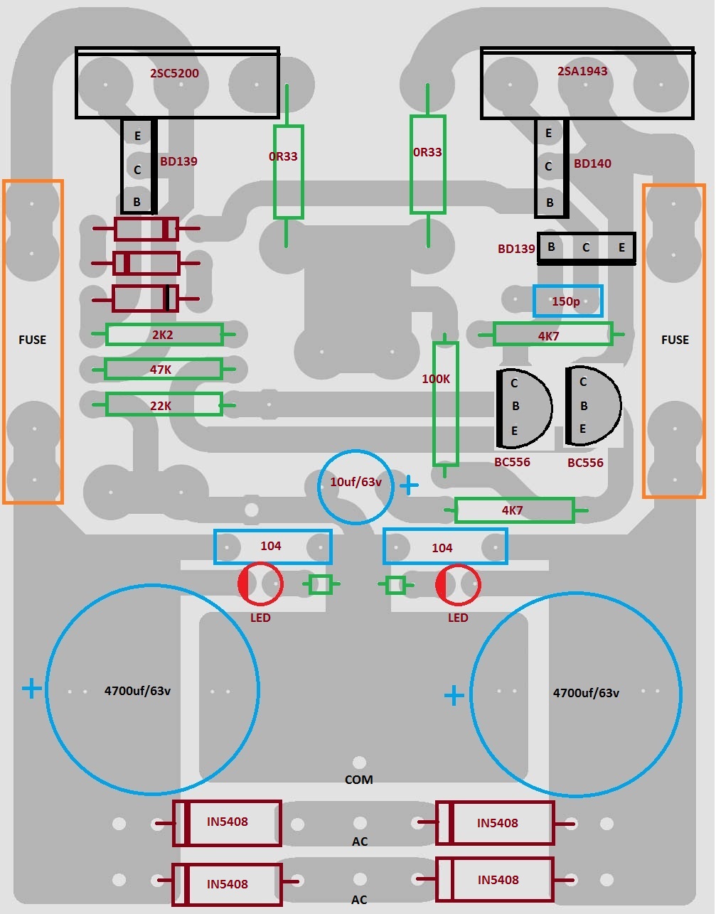
I would shift the speaker return to 5mm above the Com connection and put the 0.1 decoupling caps just above the diodes.
Ditch the led's and make the earth land wider so that the input ground and the C1 10uF/63V cap can have their individual earth connections - the ground for that NFB shunt cap is critical and should not be tangled with any other earth currents.
Also the input is shorted to ground !.
Also shift the output connection up to the middle of the land, and the R5 connection down.
Keep up the good work,
Eric.
Thank you very much Sir.
All parts are in, now first will make one amp and test it .. then make five more for my 6 Channal amp build.
Rakesh, how many amps and how many volts (secondary) in your transformer?
Six Channal Amp with 27-0-27 AC 8amp Transformer.
thanks rakesh... i will try to build one too.
maybe my 15 amps transformer will be alright.. with 5 channels
Last edited:
Nice to hear that Sir,,
Are you planning to use single or multiple PSU ..
I am using one PSU per AMP.... made on same PCB..
sir i'm planning to use 1 psu for all the amps. but is it ok with same transformer?
sir what is the size of your pcb?

sir i'm planning to use 1 psu for all the amps. but is it ok with same transformer?
sir what is the size of your pcb?
I think its ok to power all amp with one single transformer and multipal PSU Circuit.. Until and unless tranformer have that much juice..
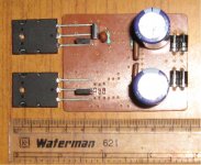
PCB Size = 7cm x 5.5cm
Work under progress
Attachments

I think its ok to power all amp with one single transformer and multipal PSU Circuit.. Until and unless tranformer have that much juice..
PCB Size = 7cm x 5.5cm
Work under progress
thanks sir..
have u tested your unit?
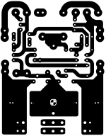
Could you post the component overlay for your board.Test Amp construction under process...
- Status
- This old topic is closed. If you want to reopen this topic, contact a moderator using the "Report Post" button.
- Home
- Amplifiers
- Solid State
- DIGI-125 Kit Amplifier Module