Hey folks,
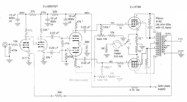
I am hoping you fellas can help me track down a problem with my just finished DIY amp. First alittle background. I started with the Plitron design
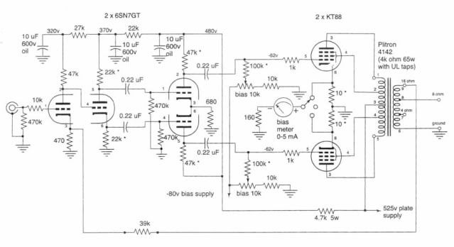
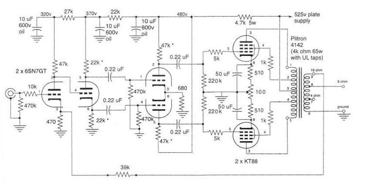
I then changed it to auto-bias on the output stage and build the following
I built the amp with Plitron torodial OPTs and used ASC motor run caps (bypassed with 1uF Solen films). Well here is the problem. I am getting massive oscillations on the output stage. I am getting a oscillation of about 9W on the 4ohm load at 488KHz !!! When I power up the amp everything seems normal until the tubes warm up, then the oscillations build until it basically runs rail to rail . I have disconnected the NFB and even pulled the 6SN7 tubes out. None of these has helped. I have gone over and over the circuit and I cannot find any wiring mistakes. I am using a 5k grid resistor and a 1k resistor on the screens, both of which are suppose to prevent this parasitic oscillation.
Frankly folks I am stuck, I don't know where to continue with tracking down the problem.
I am hoping you fellas can help me track down a problem with my just finished DIY amp. First alittle background. I started with the Plitron design
I then changed it to auto-bias on the output stage and build the following
I built the amp with Plitron torodial OPTs and used ASC motor run caps (bypassed with 1uF Solen films). Well here is the problem. I am getting massive oscillations on the output stage. I am getting a oscillation of about 9W on the 4ohm load at 488KHz !!! When I power up the amp everything seems normal until the tubes warm up, then the oscillations build until it basically runs rail to rail
. I have disconnected the NFB and even pulled the 6SN7 tubes out. None of these has helped. I have gone over and over the circuit and I cannot find any wiring mistakes. I am using a 5k grid resistor and a 1k resistor on the screens, both of which are suppose to prevent this parasitic oscillation. Frankly folks I am stuck, I don't know where to continue with tracking down the problem.
Last edited:
You need to go learn a little about HF stability margins and lag compensation networks. You have too much HF gain and too little phase margin. Start with Jones "Valve Amplifiers 3rd Edition" or Radiotron Designer's Manual 4th Ed..
I doubt that the change from fixed bias to cathode bias would cause this issue, but building designs not as intended can lead to this result. It is possible that ESL in the cathode bypass capacitors has affected the phase margin at very high frequencies, but the lack of any sort of compensation is questionable as you must assure that loop gain is below unity at the point where closed loop phase shift reaches 180 degrees or you will have an oscillator.
Cathode biased output stages are not a choice I would make and given just how critical DC balance is with a toroid OPT I would probably not have made this choice. Look into Baxandall's garter bias if you must use cathode bias. Note that the change from fixed to cathode bias probably significantly reduced the maximum available output power as well, and requires a commensurate boost in plate voltage to maintain the same quiescent and small signal operating points. (Large signal is a lost cause as the bias will shift towards class B at higher powers anyway.) Your plate voltage should increase by the amount dropped across those cathode resistors and I also suspect that the very high idle current is on the verge of cooking those tubes.. (I'll swag it is more than 100mA per tube)
Also noted that you changed the 100K grid resistors to 220K which has the effect of increasing open loop gain by several dB which helps make your problem worse and is also not a good idea with crummy modern KT88 due to their excessive grid current, and the possibility that as they get hot they will run away and self destruct.
Last edited:
If I am not mistaken both phase and gain margin only refers to the use of NFB, as the feedback becomes positive with the phase shift caused by passive networks. As I mentioned somewhere in my post I have disabled the NFB in my circuit, even going as far as to pull the 6SN7 tubes.
RF oscillation in UL outputs is not uncommon. It means your OPT is less than perfect. The usual solution is snubber networks between each output anode and g2. Try starting with 1K in series with 1nF, and adjust as necessary. This is nothing to do with overall global feedback stability.
On a separate issue, what happen when the balance slider lifts off the balance pot? Does it make the cathode decouplers go bang?
On a separate issue, what happen when the balance slider lifts off the balance pot? Does it make the cathode decouplers go bang?
Please post pictures of the layout as your comments indicate a possible construction related issue.
Also recheck to make sure that there are no obvious wiring errors.
Those 1K grid stoppers should be right at the socket and I would recommend stoppers on the screens as well - quite possible this is contributing to the issue. Something in the range of 220 - 330 ohms ought to work well. DF96's comment shouldn't be the case here, but as a last resort a snubber can be used across the primary as he suggests. Given the very high quality of your OPT this should absolutely not be necessary.
Should the balance pot wiper go open it is possible for very high voltages to appear across the cathode bypass caps so depending on the voltage rating of those caps it is possible that something untoward could happen. The solution would be to put a couple of 220 - 470 ohm power resistors from each end of the pot to the wiper. (Just something to maintain a current path - operating point will obviously shift, you need to choose resistors large enough to not adversely impact adjustment range, but small enough to maintain reasonable current through the output stage.)
Last edited:
I might be confusing the tube terminology here, but in the schematic I built (the lower one) there is a 5k resistor on the grid and a 1k resistor on the screen.
I am really trying to avoid having to go back to the upper schematic, as it's a serious bit of work. I would really hate to rebuild the output stage only to have it still oscillate. And given the fact that at AC the cathodes are both grounded, I fear changing the output stage back to grid bias will have no effect other then to test my patience.
I am really trying to avoid having to go back to the upper schematic, as it's a serious bit of work. I would really hate to rebuild the output stage only to have it still oscillate. And given the fact that at AC the cathodes are both grounded, I fear changing the output stage back to grid bias will have no effect other then to test my patience.
I'm rather surprised that the upper circuit would be stable with no dominant pole compensation or lead network. That said...
With no feedback, you're asking for trouble unless your grounding is perfect (no such thing), you have everything properly bypassed to the correct points, and you have avoided any other seemingly negligible and subtle HF positive feedback path.
If it were my amp, I would restore the feedback (the gain will be ridiculously high otherwise), snub the UL connections as DF96 suggests, and put a dominant pole in the first stage (RC network across the plate resistor). The whole advantage to a toroid transformer is that it pushes the HF poles far enough up that you can get away with reasonable levels of feedback without having to drop open loop bandwidth too far.
It is just about possible (but, I admit, unlikely) that going from 1K to 5K for the g1 stoppers is part of the problem. Whatever effect the g1 stopper has, will happen at about 5 times lower frequency now. Remember, to get oscillation you need both gain and phase shift.
It is difficult to build an audio output using RF type practices, because lead lengths are naturally higher, but it is always good to remember that the valves don't know what frequency range they are meant to be amplifying. Is there any scope for capacitive feedback from OPT leads to the body of the coupling capacitors, for example? If you ground the output grids, either before or after the grid stopper, does the oscillation cease or change? A general rule: if changing it affects the oscillation, then it is part of the oscillator.
If you can do GHz, then 488kHz is almost DC!!
Last edited:
If I am not mistaken both phase and gain margin only refers to the use of NFB, as the feedback becomes positive with the phase shift caused by passive networks. As I mentioned somewhere in my post I have disabled the NFB in my circuit, even going as far as to pull the 6SN7 tubes.
I think you are right. With the 6SN7s pulled there's no NFB loop. The only thing I can think of is that you have got the screen connections crossed which might turn this into a really nice power oscillator.
If the problem exists with the 6SN7s pulled then that is where to start. Pull them then ground the grids of the output tubes and see if it still occurs.
Cheers
Ian
Last edited:
Ok update here. I just applied the NFB. It now oscillates at 60Hz ... but that is from the hum problem (one problem at a time). When i leave the NFB (so now there is a reference to ground) but pull the input 6SN7 the oscillation is GONE !!!! I suspect that if i track down the source of my hum I will be good to go.
So this brings up another question, how much 60Hz swing should I see at the output of each of the stages ?
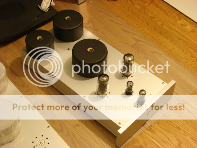
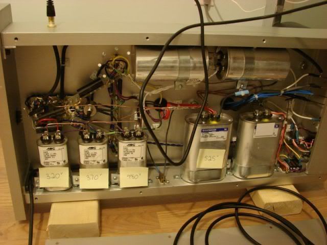
I built this tube amp many many years ago. Building it totally put me off DIY audio and high end audio period. I picked up flying RC helis and let the amps collect dust. I got bored this winter and decided to try and finish the things off. So please don't judge my HORRIBLE layout on my current engineering skills
So this brings up another question, how much 60Hz swing should I see at the output of each of the stages ?
I built this tube amp many many years ago. Building it totally put me off DIY audio and high end audio period. I picked up flying RC helis and let the amps collect dust. I got bored this winter and decided to try and finish the things off. So please don't judge my HORRIBLE layout on my current engineering skills
I think I have the parasitic oscillation problem solved. I now have the following issues
- It seems i am getting a lot of 60Hz on my input stages
- Not entirely sure I am applying NFB, might be PFB, i am not sure I have the proper inversions wired up properly
- Not sure about my bias currents. the KT88 are drawing 85mA each, which i was under the impression I was suppose to aim for 50mA.
P.S. I really appreciate all of your FAST responses and interest. As much as this is driving me nut I am starting to remember why i use to love DIY audio.
Ok here is the amp, please be gentile
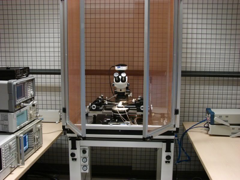
BTW Here is my day job (I am a doctrate student, so while I don't get paid I still call it a job).
- It seems i am getting a lot of 60Hz on my input stages
- Not entirely sure I am applying NFB, might be PFB, i am not sure I have the proper inversions wired up properly
- Not sure about my bias currents. the KT88 are drawing 85mA each, which i was under the impression I was suppose to aim for 50mA.
P.S. I really appreciate all of your FAST responses and interest. As much as this is driving me nut I am starting to remember why i use to love DIY audio.
Ok here is the amp, please be gentile
BTW Here is my day job (I am a doctrate student, so while I don't get paid I still call it a job).
This doesn't look too bad at all.
It is quite possible that you are in fact applying positive feedback and the easiest thing to do in this case would be to swap the connections from the final driver stage to the output tubes. Do this only after observing oscillation with the feedback applied and none without.
The 60Hz hum could be coming from your filament wiring or the interface between the filaments and their respective cathodes. Both are easily fixed.
In the case of wiring make sure all filament lines are tightly twisted and placed away or at right angles to sensitive circuitry. Make sure you have not created a large loop with the filament wiring around the sockets, if so rearrange to minimize the loop area as much as possible - best if the wires are twisted right up to and going away from the socket. I am assuming that you are not using the chassis for filament returns - if you are go back and fix that.
Generally applying some dc bias to the filament windings is a good idea to turn off potential diode effects between the filament and cathode. Generally a simple resistive divider capacitively decoupled to ground and connected to a filament transformer center tap or one side of the filament wiring will suffice. You need to select a voltage such that the filament to cathode insulation voltage ratings are not exceeded anywhere. 50 - 60V should suffice in most cases. Use a large enough capacitor to assure that the impedance of the node is reasonably low at 60Hz.. Aim for about 1mA of current in the resistive divider and choose an appropriate capacitor.
85mA bias seems not too unreasonable given your use of cathode bias, however dissipation is pretty close to the maximum tube rating so it could be that 560 - 600 ohm bias resistors would be a better choice. The 50mA value is most appropriate for fixed bias in this design. Once everything is sorted out look for signs of red plating in your KT88s. It's a bit unfortunate that you did not stick with the original fixed bias, but I think this will work well enough.
Fix one issue at a time... Post with further questions and we'll try to help.
Last edited:
Ok, I just measured the 60Hz hum on the 2nd 6SN7 stage and the KT88 stage. Both are about 2mV which is small enough I believe. I believe all of the hum is coming from the input stage (I will measure that shortly).
I am concerned about the 85mA bias on the KT88, is that way too much ?
Correction, what I thought was hum isn't 60Hz at all. It is all kind of very low frequency artifacts, my scope frequency measurement is jump all around 5-15Hz. I have a feeling this isn't actually coming from my amp but simply due to my test setup.
Last edited:
Ok, I just measured the 60Hz hum on the 2nd 6SN7 stage and the KT88 stage. Both are about 2mV which is small enough I believe. I believe all of the hum is coming from the input stage (I will measure that shortly).
I am concerned about the 85mA bias on the KT88, is that way too much ?
Correction, what I thought was hum isn't 60Hz at all. It is all kind of very low frequency artifacts, my scope frequency measurement is jump all around 5-15Hz. I have a feeling this isn't actually coming from my amp but simply due to my test setup.
The second stage hum is reasonably low and should cancel as long as it is all common mode. (In phase on both phases) Voltage regulation of the mains is imperfect and a lot of what you are seeing in the very low frequency region may be nothing more than slow, long term variations in the line voltage. Probably not an artifact of your measurement setup. I see much the same thing here, but at much lower frequencies of a couple of Hz or less, sure that is not what you are seeing?
The bias is a bit on the high side IMHO, but again look for signs of obvious distress and I would ultimately change those resistors as I remarked.
- Status
- This old topic is closed. If you want to reopen this topic, contact a moderator using the "Report Post" button.
- Home
- Amplifiers
- Tubes / Valves
- Problem with my amp, and I have run out of ideas