^ That board looks great!

I've already got some polypropylene film caps which I'm planning to use, so I'll probably go for 4.7uF per channel for now. Unfortunately no one seems to stock the Dayton foil caps in the UK, but PE do seem to offer international shipping if I do order some of the foil caps from them, then I should be able to swap out my polypropylenes without too much trouble.
For removing the AK4393's I'm going to use Quik Chip which is great stuff as it lowers the melting point of the solder holding the chip down so I'm hoping I can remove the old DAC's without lifting any traces.
I'll be sure to try and keep the chip as cool as possible while soldering it though, in fact I've got 5 x AK4396's and also a spare DCX in case I don't at first succeed... but I'm hoping I won't have to use the spare DCX!
Just to confirm, when you said 'short the now open inputs to the opamps, too.', do you mean connect the signal lines going to the op-amps to ground? If so that sounds easy enough so I'll do that.
I've got some thick flux which also seems pretty gelatin like, do you apply it to all the pads before placing the chip down, or do you add it to each leg just before soldering it?
In fact I've already removed the DSP board and also removed those 6 capacitors right next to the DAC's in order to make a little more room while removing the DAC's - the ones marked C6, C7, C8,C9,C10 and C11.
I already have some 25v 15uF OSCON's on hand which fit, would it be ok to use these or would be be best to use the same value as the original caps - 10uF?
Finally, I've noticed that the DSP board seems to contain quite a lot of 10uF/25v capacitors, I'm tempted to upgrade the whole lot to OSCON's... Would there be much benefit in doing this?
IE. Has anyone already done this already and noticed much improvement in the sound?
Thanks... Now I've opened my DCX I was going to say that it does look rather different to that pic I posted...Not sure if this is important but the pic above is not from a DCX.
jan didden
Thanks, I'm going to go with the capacitor option for now.The direct out mod for the DCX2496 eliminates all of the circuitry after the dac chip, taking the analog output straight out of the chip through a stack of foil coupling caps to the xlr pins. I have tried many different active outputs with opamps and none can compare to the transparency of running direct as has also been discussed regarding the CS4398 dac chips here. Jensen JT-11-EMCF transformers also sound excellent but get expensive when six are needed for a DCX.
.
http://www.diyaudio.com/forums/digital-line-level/137976-experience-diy-dac.html#post1735158
.
The ribbon wires between the digital and output boards are cut to get the audio signal before being polluted by any cheap coupling caps,balanced to single ended conversions, active filters and single ended back to balanced conversions with servo shifting output. This eliminates a series of 4 opamps and countless capacitors and resistors which yields unbelievable sonics with a slight loss of gain. If you want to try it yourself, the wires that you need starting from the red are 3-14 for the outputs from 6- to 1+ in that order. Note that counting from the red is the opposite to the way the wires are numbered on the schematic. The Dayton foil caps were chosen in listening tests over several other popular film type caps. In general I can safely say after trying tens of different high end caps that were recommended to me, that a good foil cap will sound much better than any poly film cap in a critical application such as this. The AudioCap Theta or ridiculously over priced boutique types such as the MIT should also give good sonics but the Daytons maintain a price performance advantage of 500% over the next reasonably priced contender, the Thetas. There is limited empty space under the hood of the 2496 Behringers so the maximum amount of capacitance is limited to what will fit which is 4uf, 3uf, 1uf for low, mid, high in the DCX and 4uf in the DEQ.
I've already got some polypropylene film caps which I'm planning to use, so I'll probably go for 4.7uF per channel for now. Unfortunately no one seems to stock the Dayton foil caps in the UK, but PE do seem to offer international shipping if I do order some of the foil caps from them, then I should be able to swap out my polypropylenes without too much trouble.
I see, I'll be sure to take my time when cutting the output pins... So I'm assuming that only need to cut the + and - pins while leaving ground in place?The output pins are cut where they come up from the board in order to accept the signal wires from the caps and remove the connection to the stock output. Only bend the cut pins on the board side to create the open space. If you bend the output pin side it will snap off way up into the plastic of the output connector. I like the paired strands of the 1701a for hook up wire. I run these in a 8 foot length for my interconnects. They sound great and have replaced my Nordost Interconnects so the 1701a should make a nice hook up wire. The 4395 dac chip is my preference along with a dedicated voltage regulator. Or, you can use an AK4396 which will drop right in with no other mods.
Great advice, thanks. I think the DAC swap is going to be the hardest part for me, as I do find SMT tricky but I have done some SMT stuff before so I think I'll be fine if I take my time with it.Beware! The legs of these chips are tiny and difficult to solder without bridges forming. Use plenty of flux to keep the solder flowing where it belongs. Also, the chips are very fragile to heat. Use the minimum amount of time on each leg and count to ten before proceding to the next leg or use a very quick drag soldering technique. Your chances of getting three out of three working when you are done is pretty slim on your first try. It would be worth $100 of frustration to take the board and chips to a tech and let them do the swap. It is also easy to lift a trace from the board and digital boards are not available as a separate part. Don't cut pin 1. Just leave it as it is for the output ground.
For removing the AK4393's I'm going to use Quik Chip which is great stuff as it lowers the melting point of the solder holding the chip down so I'm hoping I can remove the old DAC's without lifting any traces.
I'll be sure to try and keep the chip as cool as possible while soldering it though, in fact I've got 5 x AK4396's and also a spare DCX in case I don't at first succeed... but I'm hoping I won't have to use the spare DCX!
A replacement ribbon cable does sound like a good idea, in fact I don't think my original ribbon cable was that good anyway as my DCX seems to occasionally suffer from the egg frying issue. I'm sure that this direct out mod should fix that however...I would advise to do like in the pictured mod and replace the original ribbon cable. It looks harder to begin with, but it will likely turn out to be the most clean and tidy way.
I'd then pick any signals (AOUT+ and AGND) directly from that new and very own ribbon connector, customizing it as needed.
As Jannemann correctly noted, it's a DEQ, but nevertheless.
An alternative way would be to sacrifice the original ribbon and cut the required wires just before the I/O-Board connector in order to pull the strands off the ribbon (pair wise, ideally). You'll then have the selected output channel signals available while maintaining the original input functionality. Don't forget to also cut the (probably unused, but still connected) noninverting signal lines (AOUT-). As a bonus, short the now open inputs to the opamps, too. Takes care of any possible oscillation-induced noise.
Just to confirm, when you said 'short the now open inputs to the opamps, too.', do you mean connect the signal lines going to the op-amps to ground? If so that sounds easy enough so I'll do that.
I'll do it at the ribbon cable, as I've found running wires to pads can lead to lifted traces...I will join the chorus - do it at the ribbon cable and ideally use this opportunity to replace this with your own. Be careful in counting pins/wires as it is easy to make a mistake. The other option is taking out first set of resistors where signal comes on I/O board and running thin wires from there but I really would not recommend this as it is very fragile. In any case you do not want to have any signal to go toward original output circuitry - op amps, so ether method will work for that - cutting ribbon cable or lifting resistors.
I'm going to use Quik Chip - if you search for Quik Chip on youtube there is a nice is of someone removing a big chip from a Nintendo 64, it seems to be the safest way of doing it I've seen so far...When you change DACs here is what you will need:
In ideal case - hot air solder gun - just to unsolder chip. It works like a champ, but you have to be careful not to loose any close SMD parts. I never found hot air soldering good, but for unsoldering is the best. VERY IMPORTANT - Do not pull chip until you feel that it is going off on it's own, otherwise you will pull traces EASILY!
Gotcha. Flat = good... Lumpy = bad!After you unsolder 4393s carefully clean up pads with braided wire first, to remove existing solder, and than use alcohol to clean it up. Your goal is to have a very FLAT and clean surface so when you place new chip on those pads, it sits nice and flat without wiggling.
Brilliant... I'll be sure to try a few different soldering tips, I've also found that they really really small ones can be a little useless.Use smallest gage solder you could fine. I mean the thinnest one. Do not use those very, very thin solder tips for your iron since they do not transfer any heat. More like something in the middle. If you create bridges between the pins, do not panic, just use braided wire to pick it up. Likewise braided wire has to be of really fine mesh in order to work well. As mentioned earlier, use flux in order to aid you in soldering. I use flux that is like gelatin and I put some underneath the chip in order to sort of keep chip in the place, until I solder the first pin. After that it is easy... sort off
I've got some thick flux which also seems pretty gelatin like, do you apply it to all the pads before placing the chip down, or do you add it to each leg just before soldering it?
Thanks.The most important - use ether microscope or 10x loupe in order to see what you are doing and how good are connections and if you created any bridges.
I would strongly advise you to unsolder bypass electrolytic caps that are on one side of the chips. They are really on your way when you are soldering. If you do that use that opportunity to replace them with lets say OSCONS - just suggestion.
When I work on this, I pull the whole DSP board out of the case so it is much easier to handle it and to come close to it since you most likely you will be viewing through the loupe and you have to be very close to be able to be in focus.
Good luck!
In fact I've already removed the DSP board and also removed those 6 capacitors right next to the DAC's in order to make a little more room while removing the DAC's - the ones marked C6, C7, C8,C9,C10 and C11.
I already have some 25v 15uF OSCON's on hand which fit, would it be ok to use these or would be be best to use the same value as the original caps - 10uF?
Finally, I've noticed that the DSP board seems to contain quite a lot of 10uF/25v capacitors, I'm tempted to upgrade the whole lot to OSCON's... Would there be much benefit in doing this?
IE. Has anyone already done this already and noticed much improvement in the sound?
Last edited:
The 4 transistors with the red ties around them. Andy
I was thinking you are talking about transformers - tranys.
jFets are tied together in order to keep them under equal temperature conditions, since this is balanced circuit. When tied and touching each other through termal paste they cannot be closer than they are. Obviously I electricaly matched them closely in the first place.
I'm going to use Quik Chip - if you search for Quik Chip on youtube there is a nice is of someone removing a big chip from a Nintendo 64, it seems to be the safest way of doing it I've seen so far...
I use the same, but did not have much use since hot air really does great job.
I've got some thick flux which also seems pretty gelatin like, do you apply it to all the pads before placing the chip down, or do you add it to each leg just before soldering it?
It is hard to apply it just to certain pads. I just put it over pads as one line on both sides, and than place chip over it. Like I mentioned I also put some in the middle in the area with no traces just to hold on chip little bit so it doesn't move around as I am trying to solder first pin.
I already have some 25v 15uF OSCON's on hand which fit, would it be ok to use these or would be be best to use the same value as the original caps - 10uF?
Finally, I've noticed that the DSP board seems to contain quite a lot of 10uF/25v capacitors, I'm tempted to upgrade the whole lot to OSCON's... Would there be much benefit in doing this?
IE. Has anyone already done this already and noticed much improvement in the sound?
You will be quite fine using what you have. I changed all my caps on DSP board to OSCONS. See my posts and pictures posted in this thread a long time ago. It is hard to say if I there was a difference since I changed a lot and bypass and filter caps are the least in the list of changed items that would make a noticeable and audible difference. I am sure they do something since they are much better than the ones originally installed,
http://www.diyaudio.com/forums/digi...er-dcx2496-digital-x-over-28.html#post1370646
Hi,
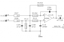
Yes. I've attached some screenshots from the DCX schematic. The first one shows the differential input of the DAC buffer (example shown for output channel one, connector X13, pins 13 and 14 on the I/O-board).
These pins should both be tied (together and) to analog ground. If left open the opamp IC1A will have an ill defined input signal and might pick up noise. This noise - and likely hum - would be amplified, which could result in parasitic supply current drawn by the opamps. We're speaking of four opamps per output channel, so 24 opamps (12 ICs) in total for all six outputs. In a worst case scenario this load would weaken regulation performance of the DCX's power supply even further - unfortunately it's very bad to begin with.
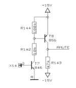
The second image shows the muting control circuit. If you feel like it, you could additionally use this one in order to permanently mute the outputs. If you don't, just keep this pin connected to the DSP board.
It won't help a lot, as those capacitors are mainly filtering the 5V and 3.3V lines to the DSP and control circuitry, only some of them are responsible for the +/-15V rails - which in turn are screwed by the PSU (and the poor regulators) anyway.
It won't hurt, though.
Just be careful with the pads and vias.
Cheers,
Sebastian.
Just to confirm, when you said 'short the now open inputs to the opamps, too.', do you mean connect the signal lines going to the op-amps to ground? If so that sounds easy enough so I'll do that.
Yes. I've attached some screenshots from the DCX schematic. The first one shows the differential input of the DAC buffer (example shown for output channel one, connector X13, pins 13 and 14 on the I/O-board).
These pins should both be tied (together and) to analog ground. If left open the opamp IC1A will have an ill defined input signal and might pick up noise. This noise - and likely hum - would be amplified, which could result in parasitic supply current drawn by the opamps. We're speaking of four opamps per output channel, so 24 opamps (12 ICs) in total for all six outputs. In a worst case scenario this load would weaken regulation performance of the DCX's power supply even further - unfortunately it's very bad to begin with.
The second image shows the muting control circuit. If you feel like it, you could additionally use this one in order to permanently mute the outputs. If you don't, just keep this pin connected to the DSP board.
Finally, I've noticed that the DSP board seems to contain quite a lot of 10uF/25v capacitors, I'm tempted to upgrade the whole lot to OSCON's... Would there be much benefit in doing this?
It won't help a lot, as those capacitors are mainly filtering the 5V and 3.3V lines to the DSP and control circuitry, only some of them are responsible for the +/-15V rails - which in turn are screwed by the PSU (and the poor regulators) anyway.
It won't hurt, though.
Just be careful with the pads and vias.
Cheers,
Sebastian.
Last edited:
chip removal
I like to cut the chips out with a razor knife and remove the legs one at a time with plenty of flux to carry the heat. I also re use the solder that remains on the pads (which will be all of it if you work carefully). This makes tacking the first leg down trickier but is much easier in the long run as adding solder back on is hard not to get too much and to do it quickly enough not to damage the chip from heat. The most sensitive part of the chip are the four analog output legs. If you get done and do not have 2.5v on each analog leg, something is fried The key to all of this is having the whole area completely submerged in a good "leave on" type of paste flux.
I like to cut the chips out with a razor knife and remove the legs one at a time with plenty of flux to carry the heat. I also re use the solder that remains on the pads (which will be all of it if you work carefully). This makes tacking the first leg down trickier but is much easier in the long run as adding solder back on is hard not to get too much and to do it quickly enough not to damage the chip from heat. The most sensitive part of the chip are the four analog output legs. If you get done and do not have 2.5v on each analog leg, something is fried The key to all of this is having the whole area completely submerged in a good "leave on" type of paste flux.

Effect of additional passive highpass
My system is built around Acoustat 1+1 electrostatic speakers with subwoofers and supertweeters to extend frequency response and dynamic range.
The supertweeters are Elac 4pi II which have a built-in passive highpass of some kind. (This is the older version which did not have adjustable crossover like later models.) For the sake of argument, assume the built-in highpass has 12dB/octave cutoff below 8kHz.
I'm trying to augment my system with this supertweeter above 14kHz with as sharp a cutoff as possible. But playing with DCX, it appeared that I had to set crossover as high as 16.5kHz to achieve a 14kHz acoustic cutoff. These measurements are extremely difficult to make and I could be in error.
But I've started wondering if the passive highpass of the supertweeters is somehow detuning my sharp LR48 cutoff. My intuitions on this go both ways, and I haven't worked the math for decades and am a little bit afraid to try.
On the one hand, you might think the additional buffered non-interacting highpass could only make the ultimate acoustic highpass curve even steeper. (But here, the trick word is "ultimate", other stuff might go on before you get there). OTOH, if LR48 is about as steep as you can get, anything you change might make it worse.
While I am at it, here is the pasive output board I am just finishing. Lundahls and ballanced jFet buffers!
Hello !
Would you share schematics for the output Jfet buffers, and connection with Lundhal ?
Thanks
Hello !
Would you share schematics for the output Jfet buffers, and connection with Lundhal ?
Thanks
It's right here
http://www.diyaudio.com/forums/digi...er-dcx2496-digital-x-over-57.html#post2363070
The only difference from schematic is that I changed connection on Lundahls from1:8 to 1:4. For that as I mentioned, RC filter is 9K and 680pF
Thanks for the advice sendler, sek and AR2, I'll be sure to keep it in mind once I get around to swapping DAC chips.
For now I've only done the direct out mod, as I wanted to see how much difference the direct out mod would make... I ended up making a passive low-pass filter on some stripboard, using 0.033uF caps and 100R resistors, and I can easily bypass this if I choose to once I get around to swapping DAC chips.
It has made a big difference sound, the sound is more refined, and the bass and treble both seem to be more defined and overall better. I'm glad I've done this mod and I found it to be easy to do, in the end I used PCB mounted plugs then I didn't need to cut into the ribbon cable....
Here are some pics... Here is the stripboard which has the passive low pass filter in, and it also grounds the inputs to all the op-amps to avoid any noise issues:
I used 100ohm resistors and 0.033uF caps.
It's not exactly a work of art but it seems to work so I'm happy with it, I was worried the tracks may pick up noise but the outputs on my DCX seem very quiet and much better than before so it's all good.
My DC blocking caps are on the left, I used a mixture of values 6.8uF for Low channels, 4.7uF for mids, and 2.2uF caps for highs. I seemed to just about have enough room:
Testing it out, all the channels work and I'm no longer getting the infamous egg frying sound on any of the channels.
For now I've only done the direct out mod, as I wanted to see how much difference the direct out mod would make... I ended up making a passive low-pass filter on some stripboard, using 0.033uF caps and 100R resistors, and I can easily bypass this if I choose to once I get around to swapping DAC chips.
It has made a big difference sound, the sound is more refined, and the bass and treble both seem to be more defined and overall better. I'm glad I've done this mod and I found it to be easy to do, in the end I used PCB mounted plugs then I didn't need to cut into the ribbon cable....
Here are some pics... Here is the stripboard which has the passive low pass filter in, and it also grounds the inputs to all the op-amps to avoid any noise issues:
An externally hosted image should be here but it was not working when we last tested it.
An externally hosted image should be here but it was not working when we last tested it.
I used 100ohm resistors and 0.033uF caps.
It's not exactly a work of art but it seems to work so I'm happy with it, I was worried the tracks may pick up noise but the outputs on my DCX seem very quiet and much better than before so it's all good.
My DC blocking caps are on the left, I used a mixture of values 6.8uF for Low channels, 4.7uF for mids, and 2.2uF caps for highs. I seemed to just about have enough room:
An externally hosted image should be here but it was not working when we last tested it.
Testing it out, all the channels work and I'm no longer getting the infamous egg frying sound on any of the channels.
An externally hosted image should be here but it was not working when we last tested it.
Last edited:
OK I finally got to try out my new DCX. Trying it drive it with a new Gemini CDMP-1400 player. Using the XLR outs from the player I hardly get enough power to light the -30DB lights on the input to the DCX. Assuming I what to run the inputs to the DCX as high as posible what would be the best way to fix this, without adding a preamp? Andy
100R
100R is a lot of load on the dac. Did you compare the sound without the filter?
Thanks for the advice sendler, sek and AR2, I'll be sure to keep it in mind once I get around to swapping DAC chips.
For now I've only done the direct out mod, as I wanted to see how much difference the direct out mod would make... I ended up making a passive low-pass filter on some stripboard, using 0.033uF caps and 100R resistors
100R is a lot of load on the dac. Did you compare the sound without the filter?
Very nice direct out mod, Mike.
I also modded my DCX yesterday. Direct balanced output with Audiophiler-polypropylene caps according to these instructions: Blanced passive output stage for the Behringer DCX2496 (also used unbalanced instructions where applicable)
I also modded my DCX yesterday. Direct balanced output with Audiophiler-polypropylene caps according to these instructions: Blanced passive output stage for the Behringer DCX2496 (also used unbalanced instructions where applicable)
An externally hosted image should be here but it was not working when we last tested it.
An externally hosted image should be here but it was not working when we last tested it.
I measured the balanced passive out modded DCX today. It looks quite good compared to stock-DCX, which distorts mainly thr 3rd and 5th harmonics. With passive mod the distortion spectrum is mainly 2nd harmonic, and the total THD level is lower than stock.
The DCX was measured with EMU 0404 USB (from which I have measured THD of approx. 0,0005%), with digital input and unbalanced output. I will measure the DCX with balanced interconnects next week. I have understood that balanced signal reduces even order harmonics, so one could hope that DCX distorts even less with balanced connection.
The DCX was measured with EMU 0404 USB (from which I have measured THD of approx. 0,0005%), with digital input and unbalanced output. I will measure the DCX with balanced interconnects next week. I have understood that balanced signal reduces even order harmonics, so one could hope that DCX distorts even less with balanced connection.
An externally hosted image should be here but it was not working when we last tested it.
An externally hosted image should be here but it was not working when we last tested it.
An externally hosted image should be here but it was not working when we last tested it.
An externally hosted image should be here but it was not working when we last tested it.
An externally hosted image should be here but it was not working when we last tested it.
An externally hosted image should be here but it was not working when we last tested it.
Legis,
Interesting measurements, thanks for that!
Can I ask you a favor? I am in a discussion in the yahoo dcx group and one member has good distortion results as you have, BUT he has quite low crosstalk between channels, about -60dB.
Could you measure the xtalk on your unit? You could for instance sweep a signal into one channel and measure in the other channel. If possible, both analog and digital input.
thanks in advance,
jan didden
Legis,
Interesting measurements, thanks for that!
Can I ask you a favor? I am in a discussion in the yahoo dcx group and one member has good distortion results as you have, BUT he has quite low crosstalk between channels, about -60dB.
Could you measure the xtalk on your unit? You could for instance sweep a signal into one channel and measure in the other channel. If possible, both analog and digital input.
thanks in advance,
jan didden
Sure! I'm glad to be able to contribute.
All measurements are made with unbalanced connections.
Analog in
EMU 0404 USB's crosstalk for reference (RMAA):
An externally hosted image should be here but it was not working when we last tested it.
DCX couple of dB's behind (RMAA):
An externally hosted image should be here but it was not working when we last tested it.
Digital in
Normal measurement for level reference because of my uncalibrated measurements
An externally hosted image should be here but it was not working when we last tested it.
Second reference measurement with cables disconnected:
An externally hosted image should be here but it was not working when we last tested it.
And the real DCX crosstalk measutement with digital in. I did the measurement by muting opposite input and output and measured the leakage between unmuted channels. I don't know about this method's accuracy...
An externally hosted image should be here but it was not working when we last tested it.
The digital in's crosstalk seems to fade to noise floor mostly, if measured correctly. Low end's crosstalk is decreased over 20dB's to over -80dB compared to analog in -situation.
-Legis
Last edited:
Forgot to measure xtalk from left input (input no. 1 in DCX) to right output (output no. 4 in DCX) with digital in.
I noticed also that I should have done the first digital in graph with same vertical scale that I used in the other graphs, to ease the direct comparison.
An externally hosted image should be here but it was not working when we last tested it.
I noticed also that I should have done the first digital in graph with same vertical scale that I used in the other graphs, to ease the direct comparison.
Last edited:
By the way, my measurements of EMU 0404 seems to be somewhat worse than it "should" be. Here's another measurement of 0404 with unbalanced connections and same sampling freq I used: RightMark Audio Analyzer test : E-MU 0404 USB loopback unbal 24b 48k

- Home
- Source & Line
- Digital Line Level
- Behringer DCX2496 digital X-over