I like this attitude.... of course I don't just look at the datasheet.
")
Yes.Are you referring to post #2900?
That's not what I said. If the common-mode range is surpassed, you're screwed. No argument about that. However, if a differential output driver consists of, say, two op-amps with each even-order distortion, this will become common-mode and will be removed by a good balanced-to-unbalanced stage. And let me tell you, there is plenty of equipment out there where this is the case (so if you would just connect only one signal pin and go directly unbalanced, the signal sounds horrible, whereas with a good diff2se it sounds fine). This distortion is a type of nonlinearity that can be corrected. The odd-order ones will not be corrected, but at least converted to pleasurable even-order by the diff2se.If the common-mode range of a preceding stage is surpassed and it distorts, going unbalanced in a subsequent stage will cancel out the even order components? I don't think so, but even if it did, there's no point, as the distortion will likely be nonlinear.
Ah, ok. I agree that high impedance drive can cause noise.By that I was referring to noise caused by high impedance drive and/or bad cabling or signal routing.
Ok, fine if you disagree. I still think that going single-ended into a differential stage means the CM loop is way too heavily involved in processing the signal, leading to distortion. Unless of course you use a balun (e.g., transformer - Lundahl or so).... what I didn't agree with was the remark that single ended drive would affect sound quality badly. It can be worse due to the lost balance in the impedances, but that's also true for the differential buffers.
Fully symmetrical layout, superior CM-induced distortion, any number of things that are not documented. However, in the absence of common-mode, I believe the signal-distortion performance of your OPA1632 to be superior.What can SSM2143 or INA134 do that OPA1632 cannot be made to do, component precision aside (i.e. assume 0.1% resistors)?
As someone with commercial interests in RF PCB fabrication, let me tell you that nowadays it is quite easy for a consumer to approach a PCB manufacturing company and get them to produce your design using a state-of-the-art PCB technology. And it's not scary expensive. Just give them the gerber files, wait a couple of days and begin soldering...The disadvantages due to the higher complexity might outweight the benefits. At least for someone without an RF PCB fab...
This is true. However, better five properly configured opamps in the signal path rather than one badly configured opamp.The tradeoff that I see is this: the differential buffers with the inverter in it's feedback loop has a much higher component count, first and foremost a second opamp (in the feedback loop), but also a far higher count of passives (compensation, etc.) with their own tolerances.
I look forward to reading your findings.I will try both alternatives.
--
Greetz,
MatchASM
I look forward to reading your findings.
I'll post as soon as I got something, but unfortunately it's exam time (cs) of the year already!
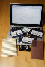
All of the most significant parts have arrived, though (see pic in fullscreen mode). I'll likely be able to get to it in about two weeks.
Cheers,
Sebastian.
Attachments
I have been planning to make balanced passive outputs with capacitors to DCX according to these instructions:
- passive output stage for DCX2496
- Blanced passive output stage for the Behringer DCX2496
What functions do I lose, if any? (besides the ability to amplify the output voltage). My logic says that is the only lost function, but am I correct?
I figured since the channel balance (when volume is decreased below 0dB) is made digitally, (and vice versa made by opamps if amplified >0dB ie. +1 to +15dB) so I don't lose the ability to to determine channel balance if I do it by using only the scale between 0dB and -15dB, if you understand what I mean. I'm setting the channel balance currently this way, so it would not be new to me.
What happens if I set channels output level to +1 - +15dB - nothing?
Last edited:
I have been planning to make balanced passive outputs with capacitors to DCX according to these instructions:
- passive output stage for DCX2496
- Blanced passive output stage for the Behringer DCX2496
What functions do I lose, if any? (besides the ability to amplify the output voltage). My logic says that is the only lost function, but am I correct?
I figured since the channel balance (when volume is decreased below 0dB) is made digitally, (and vice versa made by opamps if amplified >0dB ie. +1 to +15dB) so I don't lose the ability to to determine channel balance if I do it by using only the scale between 0dB and -15dB, if you understand what I mean. I'm setting the channel balance currently this way, so it would not be new to me.
What happens if I set channels output level to +1 - +15dB - nothing?
All these issues are of course solved with my mod - the active, remote controlled level control for the DCX. Balance, amplification, level offset between channels, and IR remote control with a volume display on the DCX.
May not be your cup of tea but hard to beat for functionality and performance. If I may say so myself
http://www.linearaudio.nl/6chan-1.htm
jan didden
Thanks Jan. What issues there will be then exactly? Is the ability to amplify output voltage the only function that is lost?
Thanks Jan. What issues there will be then exactly? Is the ability to amplify output voltage the only function that is lost?
That's not a great loss. The DCX is originally set up for pro output levels which are too high anyway. So going passive after the DAC is OK level-wise if you don't attenuate. (I also have a passive output mod described in an audioXpress article).
But when you go digital in (and you want to do that, with Frank Oettle's mod), you need a level control somewhere and the DCX has too little range as you noted. So you need an analog control somewhere betwen the DCX and your power amps. You also want to set the levels of the different channels separately as you may have different amps and different driver sensitivities.
That was the point I decided to fix it once and for all
jan didden
I have an Yamaha AV-receiver with 7.1 inputs and 7.1 pre outs as a 6ch volume controller after the DCX. It is nice, but maybe not the most hi-fi solution on the market. For the price it's nice though; one can get good deals for couple of years old AV-receivers.
So I think I can go passive without sacrificing anything? The DAC has full amplitude digital signal at it's digital input, I set channel balance by only attenuating channels (between 0dB and -15dB), the final volume is controlled by the AV-receiver and from there the signal is finally taken to the power amps.
receivers tend to have VERY noisy preamps.
I tried using my older yamaha as an amp (using their 'pure direct' mode) and it was quite noisy at 0db gain and only at about -20db would the noise be low enough to use.
it seems their amp sections are not too bad but the preamp is the weak spot.
you will lose a lot of performance going from dcx to a home AVR.
[snip]As for AVR's having noisy pre sections, my experience doesn't agree; neither my old Pio or newer Onkyo are particularly noisy, even with high efficiency speakers.
I would agree; while there are always cases like that, it certainly is not common. Maybe the 'noisy' case was with lower-than-usual input signal.
jan didden
I guess noise is relative, then. I'm using fairly low noise equipment whenever I can and often the preamp and dac stages end up in a headphone amp and if there is noise or flaws in the chain, you'll hear it.
perhaps I was not fair in how I tested the avr; but I set its volume control to 0db hoping it would minimize any preamp stages. it allows you to go in the positive gain direction (up to 20 or 30) and its super noisy then, but even 0 gives hiss in my spkrs when I get right next to them. all my other gear does not (hafler dh200, some diy amps, even the lm3886 chipamp). the 2 yamahas (5.1 systems from about 5-8 yrs ago) are acceptable at -20db or so (on their display) but beyond that, they get very noisy very fast.
and again, its relative. that older yamaha is still quiter than a lot of the music that gets/got released by so-called pros. you can still hear noise levels in material so the equipment is not *that* bad for playback; its just that those all-in-1 boxes don't concentrate on low-noise on their pre sections. my sample size is 2 yamahas that were a few model years apart but I can't believe that this is unique. not to mention that the avr buying audience would not know real hifi, generally (they are buying a convenience box and not a serious audio system).
I would agree; while there are always cases like that, it certainly is not common. Maybe the 'noisy' case was with lower-than-usual input signal.
jan didden
nope, not in this case. I could feed things hot or not (lol) and its because I was doing relative comparisons that I concluded the avr chain was too noisy to be useful (again, I wanted it as a simple 2ch amp, feeding in a 2v analog signal from a decent dac).
at the time I was fighting some hum problems on my hafler (physical trafo hum). I loved the hafler sound but the trafo could be heard across the room when it was very quiet (at night, say). I had a couple of yamaha avr's from a few years ago and I toyed with the idea of just using it as a 'headless' 2ch amp, leaving its vol at 0 and treating it as a slaved amp. it solved the trafo hum alright (no phys chassis noise) but the hiss level was now the problem. even in their 'pure direct' mode (bypasses tone and other crud in the path, in theory at least) there was noticeable noise.
I'm now using some diy chip-amps and while they don't have the drive of the hafler, they have none of its trafo hum; and there's nearly no hiss (lower than all my other spkr amps) from the chipamp. this means (getting back to your comment) that its not my source or dac or signal levels. it really was that the yamaha kind of sucked on its pre- stage and its not really defeatable by setting the vol control to 0. you always go thru it.
Direct out mod with AK4396
Hi, I'm looking to do replace the AK4393's with AK4396's, then do the direct out mod, using a single cap on each channel to block DC in the signal.
I've got all the parts I need I think, but I've got few questions about the direct out mod before I start soldering... I plan to DAC swap first, then test the unit then go for the direct out mod.
I've only seen a few pictures of completed but I've also seen the schematics so I know that I can use the AOUT signals straight from the ribbon cable from the DSP board.
Now, I've seen a photo a direct out modded DCX on the Yahoo group which has had the direct out mod here:
And it appears that the signal is going directly to the legs of the XLR pins on the original IO board. Now if I do the same thing, so I need to cut the legs of the IO board in order to stop the signal going into the IO board? Or would removing some components on the IO board (resistors?) be a better option in order to stop the signal reaching the op-amps on the IO board. Or am I worrying over nothing here?
Finally am I right in assuming the it's best to also get AGND from the ribbon cable also?
Thanks
Hi, I'm looking to do replace the AK4393's with AK4396's, then do the direct out mod, using a single cap on each channel to block DC in the signal.
I've got all the parts I need I think, but I've got few questions about the direct out mod before I start soldering... I plan to DAC swap first, then test the unit then go for the direct out mod.
I've only seen a few pictures of completed but I've also seen the schematics so I know that I can use the AOUT signals straight from the ribbon cable from the DSP board.
Now, I've seen a photo a direct out modded DCX on the Yahoo group which has had the direct out mod here:
An externally hosted image should be here but it was not working when we last tested it.
And it appears that the signal is going directly to the legs of the XLR pins on the original IO board. Now if I do the same thing, so I need to cut the legs of the IO board in order to stop the signal going into the IO board? Or would removing some components on the IO board (resistors?) be a better option in order to stop the signal reaching the op-amps on the IO board. Or am I worrying over nothing here?
Finally am I right in assuming the it's best to also get AGND from the ribbon cable also?
Thanks
Direct out mod
The direct out mod for the DCX2496 eliminates all of the circuitry after the dac chip, taking the analog output straight out of the chip through a stack of foil coupling caps to the xlr pins. I have tried many different active outputs with opamps and none can compare to the transparency of running direct as has also been discussed regarding the CS4398 dac chips here. Jensen JT-11-EMCF transformers also sound excellent but get expensive when six are needed for a DCX.
.
http://www.diyaudio.com/forums/digital-line-level/137976-experience-diy-dac.html#post1735158
.
The ribbon wires between the digital and output boards are cut to get the audio signal before being polluted by any cheap coupling caps,balanced to single ended conversions, active filters and single ended back to balanced conversions with servo shifting output. This eliminates a series of 4 opamps and countless capacitors and resistors which yields unbelievable sonics with a slight loss of gain. If you want to try it yourself, the wires that you need starting from the red are 3-14 for the outputs from 6- to 1+ in that order. Note that counting from the red is the opposite to the way the wires are numbered on the schematic. The Dayton foil caps were chosen in listening tests over several other popular film type caps. In general I can safely say after trying tens of different high end caps that were recommended to me, that a good foil cap will sound much better than any poly film cap in a critical application such as this. The AudioCap Theta or ridiculously over priced boutique types such as the MIT should also give good sonics but the Daytons maintain a price performance advantage of 500% over the next reasonably priced contender, the Thetas. There is limited empty space under the hood of the 2496 Behringers so the maximum amount of capacitance is limited to what will fit which is 4uf, 3uf, 1uf for low, mid, high in the DCX and 4uf in the DEQ. The output pins are cut where they come up from the board in order to accept the signal wires from the caps and remove the connection to the stock output. Only bend the cut pins on the board side to create the open space. If you bend the output pin side it will snap off way up into the plastic of the output connector. I like the paired strands of the 1701a for hook up wire. I run these in a 8 foot length for my interconnects. They sound great and have replaced my Nordost Interconnects so the 1701a should make a nice hook up wire. The 4395 dac chip is my preference along with a dedicated voltage regulator. Or, you can use an AK4396
which will drop right in with no other mods. Beware! The legs of these chips are tiny and difficult to solder without bridges forming. Use plenty of flux to keep the solder flowing where it belongs. Also, the chips are very fragile to heat. Use the minimum amount of time on each leg and count to ten before proceding to the next leg or use a very quick drag soldering technique. Your chances of getting three out of three working when you are done is pretty slim on your first try. It would be worth $100 of frustration to take the board and chips to a tech and let them do the swap. It is also easy to lift a trace from the board and digital boards are not available as a separate part. Don't cut pin 1. Just leave it as it is for the output ground.
.
Hi, I'm looking to do replace the AK4393's with AK4396's, then do the direct out mod, using a single cap on each channel to block DC in the signal.
I would advise to do like in the pictured mod and replace the original ribbon cable. It looks harder to begin with, but it will likely turn out to be the most clean and tidy way.
I'd then pick any signals (AOUT+ and AGND) directly from that new and very own ribbon connector, customizing it as needed.
As Jannemann correctly noted, it's a DEQ, but nevertheless.
An alternative way would be to sacrifice the original ribbon and cut the required wires just before the I/O-Board connector in order to pull the strands off the ribbon (pair wise, ideally). You'll then have the selected output channel signals available while maintaining the original input functionality. Don't forget to also cut the (probably unused, but still connected) noninverting signal lines (AOUT-). As a bonus, short the now open inputs to the opamps, too. Takes care of any possible oscillation-induced noise.
Last edited:
I will join the chorus - do it at the ribbon cable and ideally use this opportunity to replace this with your own. Be careful in counting pins/wires as it is easy to make a mistake. The other option is taking out first set of resistors where signal comes on I/O board and running thin wires from there but I really would not recommend this as it is very fragile. In any case you do not want to have any signal to go toward original output circuitry - op amps, so ether method will work for that - cutting ribbon cable or lifting resistors.
When you change DACs here is what you will need:
In ideal case - hot air solder gun - just to unsolder chip. It works like a champ, but you have to be careful not to loose any close SMD parts. I never found hot air soldering good, but for unsoldering is the best. VERY IMPORTANT - Do not pull chip until you feel that it is going off on it's own, otherwise you will pull traces EASILY!
After you unsolder 4393s carefully clean up pads with braided wire first, to remove existing solder, and than use alcohol to clean it up. Your goal is to have a very FLAT and clean surface so when you place new chip on those pads, it sits nice and flat without wiggling.
Use smallest gage solder you could fine. I mean the thinnest one. Do not use those very, very thin solder tips for your iron since they do not transfer any heat. More like something in the middle. If you create bridges between the pins, do not panic, just use braided wire to pick it up. Likewise braided wire has to be of really fine mesh in order to work well. As mentioned earlier, use flux in order to aid you in soldering. I use flux that is like gelatin and I put some underneath the chip in order to sort of keep chip in the place, until I solder the first pin. After that it is easy... sort off
The most important - use ether microscope or 10x loupe in order to see what you are doing and how good are connections and if you created any bridges.
I would strongly advise you to unsolder bypass electrolytic caps that are on one side of the chips. They are really on your way when you are soldering. If you do that use that opportunity to replace them with lets say OSCONS - just suggestion.
When I work on this, I pull the whole DSP board out of the case so it is much easier to handle it and to come close to it since you most likely you will be viewing through the loupe and you have to be very close to be able to be in focus.
Good luck!
Last edited:
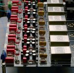
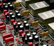
NICE, Why are the tranys tyed together? Andy
I am not sure that I understand your question. The only point they are tied together are shields that are connected to earth/chasis ground. Could you please be more specific.
- Home
- Source & Line
- Digital Line Level
- Behringer DCX2496 digital X-over