Way back in post 7......
I commented that the 135mm dimension close to the horn mouth seemed small in comparison to the expansion of the horn.
Martinsson replied in post 10 that this dimension was intended to keep a longer L23 length.
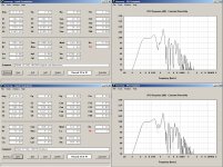
I did a best fit the horn as Martinssons original drawing, and inputted the straightened dimensional data into hornresp. This sim then shows a massive dip at 165-170 hz.
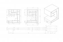
I then reworked to get a linear taper throughout the L23 section. I retained the 135mm dimension.
I did increase the S2 compression slightly from 2.18 to 2.46
This filled in the dip by 5db and made the dip W shaped.
Attached Hornresp sims and reworked dimensions
Hope this helps")
I commented that the 135mm dimension close to the horn mouth seemed small in comparison to the expansion of the horn.
Martinsson replied in post 10 that this dimension was intended to keep a longer L23 length.
I did a best fit the horn as Martinssons original drawing, and inputted the straightened dimensional data into hornresp. This sim then shows a massive dip at 165-170 hz.
I then reworked to get a linear taper throughout the L23 section. I retained the 135mm dimension.
I did increase the S2 compression slightly from 2.18 to 2.46
This filled in the dip by 5db and made the dip W shaped.
Attached Hornresp sims and reworked dimensions
Hope this helps
Attachments
Last edited:
I can give you one example from the man who actually came up with the TH idea, Tom Danley - the TH-SPUD. He released the plans to the 'net - a search for "TH-SPUD clone" should bring up a few hits.
Please point out to me where he's used "reflectors" in that design. For a sub that wide and high that's designed to do 19Hz to 125 Hz, you'd think he'd have at least one reflector in there, right?
Hmmm... interesting you brought up the SPUD... let's investigate that a little bit shall we?
Hi Eva, bjorno, all
A couple thoughts;
Eva said “In a tapped horn the phase varies wildly across the passband” and “Phase matching a mid/bass system and a tapped horn is already difficult enough.”
Perhaps in what you’re looking at but normally a measurement trumps a computer model. Simply, some features that are predicted in Akabak don’t exist in the physical item.
If your going to have faith in a prediction it has to be founded on some track record comparing with measured results. I can tell you Akabak which I use has some issues, it would be no fun at all to tell you what to do anymore than pointing out a trail.
If your first statement were true, where exactly do you see this in the measured response of say a th-215? Keep in mind, in the Tapped horns that aren’t as flat with just one unit, if you choose to eq them flat, you generally correct the phase response.
Also some Tapped horns have as little as approaching half the measured GD associated with it’s low corner compared to a vented box with the same corner F (due to it being a quarter wave 90 degree resonator and not an 180 degree inverter). This much of a difference might be audible and why they sound different.
http://www.danleysoundlabs.com/pdf/TH 215 Spec Sheet.PDF
The spud is a new product, we have not done the normal formal outdoor half space measurements yet pending time and weather.
So far as using them in a full range system, a Tapped horn is part of at least five of our full range products including the SH-50.
Keep in mind, our stand alone subwoofer products are normally used below 70-80Hz as the spud is for home theater use.
Merry Christmas, Happy Holidays and good sound to all!
Tom Danley
Hmmm.... seems like danley is saying akabak doesn't show you everything, and hornresp agrees with akabak.... hmmmm.....
Also, wonder what function you think sound absorption accomplishes in this location? hmmm.. maybe eliminating some unwanted 'reflections' or 'standing waves' ????
In a HT setup where total spl is not the goal, absorption is an option, where every db is precious, reflection is a better choice.

from here: http://forum.realmofexcursion.com/enclosures/65631-danley-dts-10-kit.html
hmmm....
AND if you follow the diyaudio thread from danley's quote above you'll see where adding additonal absorption where it wasn't necessary created a dip that hornresp said shouldn't be there, and when removed the dip was removed..... How do you suppose absorption created an extreme dip? shouldn't it have just lowered the total spl only?
Hmmm...
sorry, but not buying your TH-SPUD argument.
Hmmm.... seems like danley is saying akabak doesn't show you everything, and hornresp agrees with akabak.... hmmmm.....
No argument there. HornResp does not model box losses or the effects of lining along the path of the horn. Will return to the latter a bit later...
Also, wonder what function you think sound absorption accomplishes in this location? hmmm.. maybe eliminating some unwanted 'reflections' or 'standing waves' ????
I think they are there to absorb frequencies outside of the horn's designated passband, making x-over work and integration with a full-range system a bit easier.
AND if you follow the diyaudio thread from danley's quote above you'll see where adding additonal absorption where it wasn't necessary created a dip that hornresp said shouldn't be there
HornResp does not model the effects of absorption in the horn, so it wouldn't have anything to say about that situation.
and when removed the dip was removed..... How do you suppose absorption created an extreme dip? shouldn't it have just lowered the total spl only?
No. The level of absorption of most materials doesn't remain the same as frequency changes. Among other things, it's frequency-dependent. Also, a TH's response is the combined response from both the front and back of the driver and the use of absorbtion changes the relationship between these two, and as a result the combined result will also change, in a way that can't be predicted by HornResp.
I think they are there to absorb frequencies outside of the horn's designated passband, making x-over work and integration with a full-range system a bit easier. .
You just can't bring yourself to say that Tom uses various techniques to tackle IN BAND reflections and standing waves. From absorption in the Spud, to helmholz in the dts-20, and (most likely) oblique reflectors in the PA horns.... (last I checked, I couldn't find any real pics of the inside of a TH115.)
There ARE things you have to do in band in a TH in the folding process.... There ARE things you have to do in band... (repeat, repeat, repeat)
In the 12 step approach, you'll never get to step 12, until you start at step 1.
You just can't bring yourself to say that Tom uses various techniques to tackle IN BAND reflections and standing waves. From absorption in the Spud, to helmholz in the dts-20, and (most likely) oblique reflectors in the PA horns.... (last I checked, I couldn't find any real pics of the inside of a TH115.)
At this point you are only assuming for the Spud and the PA Horns, and you're totally wrong on why Helmholtz resonators were used in the DTS-20. They're used primarily to cut the audibility of driver distortion, not affect in-band frequency response - see PSW Sound Reinforcement Forums: LAB Subwoofer => Helmholtz resonators?
Where did the 160Hz dip go?
Nice. And no reflectors required either
.Maybe its something to do with going from a internal volume of 140 litres to 210 litresWhere did the 160Hz dip go?
Bumping up the volume, different driver, dual taper ... I'm sure all had a part in this mod. All these boxes are about 21 inches wide, and
reflections/cancellations happen side to side as well! I guess that I'll just have to make one of these and see how well it compares to the sim.
Brian: Hornresp sims the schematic layout ... we won't know what effect the folding has until we build one.
~Don
reflections/cancellations happen side to side as well! I guess that I'll just have to make one of these and see how well it compares to the sim.
Brian: Hornresp sims the schematic layout ... we won't know what effect the folding has until we build one.
~Don
Last edited:
At this point you are only assuming for the Spud and the PA Horns, and you're totally wrong on why Helmholtz resonators were used in the DTS-20. They're used primarily to cut the audibility of driver distortion, not affect in-band frequency response - see PSW Sound Reinforcement Forums: LAB Subwoofer => Helmholtz resonators?
Following on on this, have a look at Don's suggested alignment. Notice the peaks @ around 160 Hz and again around 220 Hz? These will tend make any distortion generated by 40 Hz and 80 Hz tones, and 110 and 55 Hz tones, more audible, because this distortion will be amplified by the horn by it looks like around 6dB. How to effectively deal with this? Well, EQ won't work, unless you want to cut the frequencies that are causing the distortion too. So, what's the next best solution? Two Helmholtz resonators, tuned to 160 Hz and 220 Hz might produce good results here. In fact, perhaps even another one could be added - to deal with the other peak at 340 Hz or so.
Hornresp agrees with AkAbak on a generic straight horn, yes. When you sim an actual folded horn with corners, no. Neither can get path length differences right around the corners exactly right, but the builder should be checking for this.Hmmm.... seems like danley is saying akabak doesn't show you everything, and hornresp agrees with akabak.... hmmmm.....
There is the whole small/large signal issue as well...
There is no need to wonder about it, as it has been explained. It is used to help dampen out'o band high frequencies. To help out the LP filter the bends are creating anyway.Also, wonder what function you think sound absorption accomplishes in this location? hmmm.. maybe eliminating some unwanted 'reflections' or 'standing waves' ????
If you put it in AkAbak you could see what caused the dip(s.)AND if you follow the diyaudio thread from danley's quote above you'll see where adding additonal absorption where it wasn't necessary created a dip that hornresp said shouldn't be there, and when removed the dip was removed..... How do you suppose absorption created an extreme dip? shouldn't it have just lowered the total spl only?
The extra foam raises air resistance which adds acoustic path length to the horn. It also takes away horn volume where it is located. This is what reduces amplitude, and the area of amplitude reduction depends on where the volume reduction falls along the horn path.If you build a horn, and stuff a big rubber ball in it, it won't measure like the HR sim either, but I would hardly blame the sim because you added something that wasn't put in the sim.
1/2" of light foam in the corners is not doing anything to any wave in a subwoofers passband, other than reducing the air flow volume through the horn.You just can't bring yourself to say that Tom uses various techniques to tackle IN BAND reflections and standing waves.
Last edited:
Tom Danley's notes on horns and bends...
Copied this from another thread - I'm emphasized a particular statement in bold:
"...in folding your horns, think in terms of how big is the quarter wavelength your dealing with.
What one cannot do is significantly change the total cubic volume of the interior, air is after all this curious combination of spring and mass and a "connectedness" to the outside. In making a bend, a common mistake is to assume the bend is longer than it really is. Going by cubic volume alone is close but also in a bend, the air is moving in an arc and so temporarily has slightly more mass (as the bulk of the volume is on the outer half of the radius of motion).
Also, at the frequency where the difference in path length between the inside of the bend and the outside of the bend is N 1/2 wavelengths, there are deep notches in the response. This is a result of the opposite phases recombining (and canceling out) after the bend. A good rule of thumb is make sharp bends with a short radius -or- bend angle is inversely proportional to radius). The point is again remember the "acoustic size" of what ever your dealing with. As you can see on the LAB sub the only large degree bend has a small radius (the one at the nose).
Does making the fold with a radius make a difference? Yes, it looks cool and I make them that way because something says "it should be". I have tested a couple low frequency horns with and without and to be honest it made little or no difference . Again what are the acoustic dimensions? In the LAB sub, I would suggest making at least the first two bends with the radius because it "feels right" (a non technical term I admit).
Still more complication, at the point where the wall area is a significant acoustic size, the sound pressure couples to the width mode resonance (caused by the parallel walls) which puts the first in a series of notches in the response coming out of the mouth. In this situation, there is a 1/2 wavelength standing wave with the pressure maxima at the walls and velocity max in the center. Coupling to this mode saps off energy at frequencies related to the N 1/2 wavelengths. Here, your horn mouth width (where it has parallel walls) also kind of sets your upper frequency limit
For a 21 inch wide horn like the LAB sub, the first width mode notch should be in the mid 300's which is a non issue. "
Based on these notes, I suspect the last bend in the THAM15 is what's going to create the most deviation between sim'd response and actual response, seeing it's a 180 at the wide end of the path. This afternoon I'm going to do a few calculations to see where that response difference is predicted to lie for my POC#2 (which shares the same folding), to see if it actually shows up where it should in my measurements.
Bad Brian ... Tom is talking about using an arc instead of a flat reflector. This doesn't make your point at all!
You forgot to add your smiley
.Perhaps I should have bolded Tom's subsequent rhetorical question concerning acoustic dimensions as well
.Brian,
Simming the TH as shown in the schematic, peaks are evident at 160 and 230Hz. The "Q" of these peaks is very narrow. When the TH is folded, you will
no longer have a single, unique path thru the horn, and the "Q" of these peaks will be wider and the peaks will be much lower.
Or am I wrong ...
Simming the TH as shown in the schematic, peaks are evident at 160 and 230Hz. The "Q" of these peaks is very narrow. When the TH is folded, you will
no longer have a single, unique path thru the horn, and the "Q" of these peaks will be wider and the peaks will be much lower.
Or am I wrong ...
Last edited:
Brian,
Simming the TH as shown in the schematic, peaks are evident at 160 and 230Hz. The "Q" of these peaks is very narrow. When the TH is folded, you will
no longer have a single, unique path thru the horn, and the "Q" of these peaks will be wider and the peaks will be much lower.
Or am I wrong ...
It's possible, but I suspect the answer is... I think it depends. My POC #2 doesn't show significant changes in the out-of-band peaks until +350 Hz, for example. The first "dip" seems to be deeper than expected, but that could be due to the fact that I went with a stepped config for part of the horn. I'm not sure.
At this point you are only assuming for the Spud and the PA Horns, and you're totally wrong on why Helmholtz resonators were used in the DTS-20. They're used primarily to cut the audibility of driver distortion, not affect in-band frequency response - see PSW Sound Reinforcement Forums: LAB Subwoofer => Helmholtz resonators?
still not buying....
An externally hosted image should be here but it was not working when we last tested it.
now, if this pipe is 31 3/4" long, making the total length of pipe around 40" or so, and closed end pipes are 1/4 wave resonators -- what is the fundamental of that 1/4 wave resonator? possibly around 80hz?
I know ivan is quoted as saying it was for 'distortion' reasons, and that closed pipes only resonate on the fundamental and odd order harmonics...
still I personally believe that the 2 pipes are set for fundamentals of the 2 normal peaks of a TH to tame them down, and the inductor is there to fill in the gap. As a side bonus, you also get reduction in 3rd order harmonics of the 2 'peaks' of a typical TH.
meaning, the helmholtz is there to tame a resonance that is IN BAND.... which was my point.
Last edited:
still not buying....
...even though a representative from the company specifically indicated the purpose of those pipes??
now, if this pipe is 31 3/4" long
That's a very big assumption. What if they're only 20" long?
We need to know their true lengths before making further assumptions about their purpose, particularly if those assumptions are at odds with those of the inventor
.In any case, I think you missed the major point. Theory supports the use of Helmholtz resonators to modify frequency response in a bass horn. There's no accepted theory that provides the same support for the use of "reflectors" to do the same thing.
- Home
- Loudspeakers
- Subwoofers
- THAM15 - a compact 15" tapped horn