I'd like to suggest that perhaps some sort of closed pipe or hemholtz resonator might be a predictable and effective way of dealing with the notch in the THAM15 design.
That may prove the RESULT, but not the CAUSE. (sorry Brian)
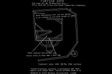
Here's an example. I know that If I put in a reflector in red where shown, it'll cut my overall response, and especially my 100hz area response.
If you're putting in the reflector exactly as shown, it's going to narrow the horn's path at that point. Not by much, but perhaps the narrowing is what's making the difference. I think that to avoid the constriction, the reflector needs to be a bit smaller so that the shortest distance from the edge of the internal panel to the reflector is somewhere between the distances of the edge of the internal panel to the two adjacent side walls. In any case, as we're talking about a bass horn, it's not really required.
Another case... a solid rear brace along the long back of that design cuts 40hz by 2db. why? more bracing should be better, and louder -- less loss through panel flex. Hollow bracing or even my 2 braces as designed in the ss15 reduce, but don't eliminate that rear panel flex. But it's louder than a solid brace.
What's the thickness of the solid brace? Perhaps the horn is sensitive to cross-sectional changes at that point.
That particular cabinet does a couple things that I don't have answers to... but again... I am just happy with the results.
...and that's probably what's most important
") .
.That may prove the RESULT, but not the CAUSE. (sorry Brian)
Good try, but the effect of pipe and Helmholtz resonators is well-documented and in line in theory. The use of "reflectors" whose effectiveness is based on the assumption that "standing waves" occur in horns below 1/2L however, is not supported by any theory
.Brian I hope you understand I'm looking for the same thing, get the theory correct behind this...
It’s not that I don’t believe in the Helmholtz resonators as a practical solution, I certainly do! But it is still fixing the problem afterwards instead of fixing the problem itself (that's why we try to find the right theory to treat problems in future on a predictable way)
Again Jbell says his “reflector” panel influence the area of 100 Hz. I see the length of the back panel is 29inch high. 29inch is = ¼ wavelengths of 116Hz. Is this again a coincidence?
Or can we really influence a signal in a horn with "reflectors" (sorry have no better word yet) at ¼ wavelengths between two parallel walls?
But it is still fixing the problem afterwards instead of fixing the problem itself (that's why we try to find the right theory to treat problems in future on a predictable way)
The theory in this case may actually give us a predictable means of fixing the problem, something we can test with modeling first before cutting wood. The more we can predict with modeling, the less need for bonfires
.Again Jbell says his “reflector” panel influence the area of 100 Hz. I see the length of the back panel is 29inch high. 29inch is = ¼ wavelengths of 116Hz. Is this again a coincidence?
It's likely coincidence. A FR and an IR test before and after the addition of the reflector may shed some light. I've pointed out though that the reflector that JBell indicated in his image would actually restrict the horn at that point - perhaps that is what is contributing to the 2dB loss at 100 Hz.
Or can we really influence a signal in a horn with "reflectors" (sorry have no better word yet) at ¼ wavelengths between two parallel walls?
I'm under the impression that reflectors in a normal horn are usually put there to improve midrange response. I don't think those are applicable to tapped horns, which have a passband that lies in the bass region.
Brian I’m not talking standing waves here...Altough... At the beginning and at the end of a standing wave it’s a zero point.. This means an amplification of the signal, right? Now, we see dips which means cancellation – out of fase.
Sanders himself seem to have influenced his Tham at 170Hz with reflectors. Jbell has given 2 examples of similar type. That it happens all around ¼ wavelength is not possible because of your theory of standing waves which is correct. But I’m talking about dips – out of fase signals. Standing waves are resulting in peaks not dips as you proved!
Now go back to my example in room acoustics of measuring at a ¼ wavelength in a full wavelength standing wave. You will see that the signal of a standing wave, that is reflected from a wall, at ¼ of its full wavelength is out of fase (look for the chapter in you books about nodes and anti-nodes)
So what theory tells you, you can’t influence a signal within a horn at ¼ wavelength???
And whitch of your theories says that anywhere in a horn, where two parallel surfaces ‘see’ each other, can't reflect a signal out of fase?
This also means you are right, you can’t influence a full wavelength with a reflector but you can prevent parallel walls that develop ¼ wavelength – out of fase – signals by the use of reflectors… And no we are not talking about standing waves we are talking about cancellation as the result of ¼ wavelength reflected by walls...
I'm not saying I'm right but I haven't seen any other explanation.... (yet)
Last edited:
Standing waves are resulting in peaks not dips as you proved!
Not correct. Check my graph. Look at what's happening at 700 Hz. That's 2*F for that particular horn/pipe geometry. And there's a null that's not predicted by HornResp.
And of course there's still the second issue to consider - the size of those reflectors - IMO they are simply too small to make any significant difference at low frequencies, reflection-wise. If they're making any difference, it's likely along what Danley and others have suggested - they're reducing the volume of the horn.
Last edited:
See, you don’t get my point. Tell me if I’m wrong but any standing wave at it’s zero point can’t be out of fase. It is causing an out of fase signal as soon the standing wave is shifted from the original signal towards a ¼ of its full wavelength.
Secondly, The reflector doesn’t reflect the wavelength because its to small. It prevents the wall surface to develop a ¼ wavelength signal…
Secondly, The reflector doesn’t reflect the wavelength because its to small. It prevents the wall surface to develop a ¼ wavelength signal…
See, you don’t get my point. Tell me if I’m wrong but any standing wave at it’s zero point can’t be out of fase. It is causing an out of fase signal as soon the standing wave is shifted from the original signal towards a ¼ of its full wavelength.
You are trying to bend an observation about the effect on a signal source 1/4L from a wall with what's going on in a horn. IMO the only time that could possibly apply is if you're talking about the distance from the horn's DRIVER to one of the horn's walls.
Secondly, The reflector doesn’t reflect the wavelength because its to small. It prevents the wall surface to develop a ¼ wavelength signal…
For the wavelengths we're talking about, I don't think it makes any difference.
I gave you 2 examples.... I have more.... and not just from me.
I also played with reflectors on my big cabinet, and the cube... so I can give you #4, and #5 as well. and guess what fraction of a wave they all line up on?
I can give you one example from the man who actually came up with the TH idea, Tom Danley - the TH-SPUD. He released the plans to the 'net - a search for "TH-SPUD clone" should bring up a few hits.
Please point out to me where he's used "reflectors" in that design. For a sub that wide and high that's designed to do 19Hz to 125 Hz, you'd think he'd have at least one reflector in there, right?
Brian, I’m still working on finding the right theories about this subject so I’m not sure yet if its only possible between driver and walls, walls & walls or any other options.
However, other peoples findings seems to prove its possible anywhere within the horn.
My theory: Cause it interrupts the signal and mirrors it in 180 degrees at ¼ of wavelength. So wherever the signal is interrupted it’s always returns backwards into the horn with a perfect shift of 180 degrees in my view…
Jbell, thanks for the sharing, oh and Brian you can use your tube you already build, seems a perfect candidate…
There is no substitute for doing.
I don't do unless I'm sure that current theory backs up what I'm doing. As a result, few times I've ever built something that doesn't measure like I expected it to, and if it doesn't, it's usually a mistake on my part rather than a problem with the theory. Stuff costs a lot more here than there, I have a lot less time on my hands than I used to, and pushing pixels is a lot easier than joining wood
.However, other peoples findings seems to prove its possible anywhere within the horn.
Any links to before/after measurements?
Jbell, thanks for the sharing, oh and Brian you can use your tube you already build, seems a perfect candidate…
Good idea. I have access to all sections of that TP, as the side panels are screwed on, not glued together. Give me some hints about where to put "reflectors", and I'll do some before and after measurements to see what difference they actually make. Better than building an entirely new horn just to test this
.Ask Jbell and Anders, they might have measurements results. Especially Jbells open field measurements seem to be a good guideline without the influence of room acoustics, you have any Jbell?
Use my tham suggestion as a guideline. Look at the grey lines from where the reflectors should start. About the steepness: Don’t make it to high cause it narrows the path. Don’t make it low cause it looses its efficiency. If two reflectors see each other it gives the maximum effect. But to many of them can make everything worse…
If you have detailed drawings it would be easier to show a suggestion.
Ask Jbell and Anders, they might have measurements results. Especially Jbells open field measurements seem to be a good guideline without the influence of room acoustics, you have any Jbell?
JBell's measurements were done at 28.3V, if I remember correctly. That's way outside what could be considered "small-signal", and as a result may or may not match the HornResp predictions.
To make this as unbiased (by me) as possible, I'll need your specific suggestions re reflector size, angle, location and dimensions. I don't have detailed drawings, but the box is basically consists of four components with internal dimensions of 6"x7.75"x19.5" built out of 3/4 ply, so it shouldn't be too difficult to work it out.
Note: any "reflectors" placed near the driver end of the line are likely to significantly change the response - and this response change can be predicted by HornResp (narrowing the line before S1).
I'll try to post a picture of the computerscreen during the testing, it may be dificult to work out, but the results where constant over a series of messurements on the two MKII's and the two originals.
Ill try to describe it, the 170 dip is the result of what seems to be several small notch cancelations, on the original there is one narrow deep dip, on the MKII there is a peak in the middle of the same dip, look at it like this, it has gone from a "V" to a "W" and the width of the dip remains the same between the two proposals.
So to my mind the reflectors seems to have had a positive impact, although being of an alomst academic nature, the results remained the same over several mesusrements wich tells me that this is not a matter of erorr in messurement.
Intresstingly enough, when messuring the MKII while running the the testsignal through the original approx one metre to the side of it, the response wha simmillar, this tells me that the reflections in the MKII are different then that of the original, even i messured passivly,t his was an intressting error in messurement though.
I do have messurement data, in file format, but i need the program (REW from hometheatrechack" to get the graphs up on my screen and make pictures of them, and being out of internet at home i can not provide them just yet, sorry.
It seems to me that the reflectors make a differance, that much is clear, but how to tune their impact seems to be a matter of emperic nature, to build and analyze, and when we get (IF we get) to see the best result we can simply back engineer from that and see how it lines up with theory.
Since I lack the deeper understanding of the theory and how to translate that into the THAM15 in form of reflector anfgles and positions testing it out seems to be the way to go, for me at last, but as i said before, my recourses are very limited at the moment.
If anyone is in the process of starting a THAM15 build and feels a bit experimental about it please let us know and perhaps we can provide a proposal of what we collectivly think is the best way to combat the dip using reflectors, when we later take part of the messurements we can see if out thinking was "correct" and perhaps learn abit in the process.
I'll try to sum up all the different proposals we have sofar.
Thanks Anders for sharing again your info and findings so far. It will be interesting to see what your plots are going to show us.
Brian, before I ‘m going to share my reflector picture I want to make sure it’s still a suggestion (although based on improvement for room acoustics).
Any comments or ideas are welcome...
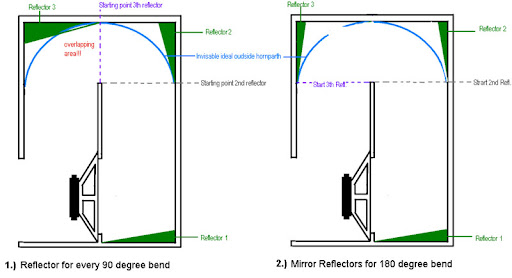
In the left part you’ll see a reflector suggestion for each 90 degree corner. The angle should be maximum 40 degrees for maximal efficiency and no less then 15 degrees for minimum efficiency.
On the right Reflector 2 and 3 have an angle of minimal 7,5 degrees and maximum 40 degrees each.
Try not to pass the blue line to much because the reflector will start to narrow the horn path from that point. Make sure that all reflectors totally cover the parallel wall. This is not possible with 45 degree corners without narrowing the horn path!
The overlaping area means where the reflector is crossing the ideal outline of the hornpath.
The reflectors hopefully work in two ways;
1.) lowering the expansion factor as result of the increased volume in a corner.
2.) minimising the reflection of 1/4 waveforms -out of fase - signals
Brian, before I ‘m going to share my reflector picture I want to make sure it’s still a suggestion (although based on improvement for room acoustics).
Any comments or ideas are welcome...
In the left part you’ll see a reflector suggestion for each 90 degree corner. The angle should be maximum 40 degrees for maximal efficiency and no less then 15 degrees for minimum efficiency.
On the right Reflector 2 and 3 have an angle of minimal 7,5 degrees and maximum 40 degrees each.
Try not to pass the blue line to much because the reflector will start to narrow the horn path from that point. Make sure that all reflectors totally cover the parallel wall. This is not possible with 45 degree corners without narrowing the horn path!
The overlaping area means where the reflector is crossing the ideal outline of the hornpath.
The reflectors hopefully work in two ways;
1.) lowering the expansion factor as result of the increased volume in a corner.
2.) minimising the reflection of 1/4 waveforms -out of fase - signals
Last edited:
- Home
- Loudspeakers
- Subwoofers
- THAM15 - a compact 15" tapped horn