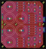
CRCRC :
First C 2 x 18,000 uF
First R 4 x 1R0
Second C 1 X 18,000 uF
Second R 4 x 1R0
Third C 7 x 2200 uF.
The last C should be high quality low ESR caps.
Simulation looks good with ripple below 100 mV and thats with RMS output current of around 5 A. Not bad at all.
Considering I will never really need 5 A RMS continously it should work very well with more "normal" loads where you only really need alot of current for transients.
I think Im done now.
Then you can start with a 20 to 22 volts transfo.
Though, I am not shure the second RC cell is necessary.
Generally, three cells are used when the voltage of the transfo is too high
Why not to follow the Nelson's scheme (increasing C values if you like). He really knows what to do.
Or, if you want a very low ripple, you can also build a cap multiplier.
Last edited:
Then you can start with a 20 to 22 volts transfo.
Though, I am not shure the second RC cell is necessary.
Generally, three cells are used when the voltage of the transfo is too high
Why not to follow the Nelson's scheme (increasing C values if you like). He really knows what to do.
Or, if you want a very low ripple, you can also build a cap multiplier.
30 V transformer, going for cascode F5.
Supply would give me around 37 Volts out with RMS load current of 4,6 A and only 66mV ripple. Load current of 8,3 A gets me 33,3 volts and 115 mV ripple. But since these numbers are continous output current, in a real world scenario with a "normal" speaker load with varying current demands the performance should be much, much better.
Could follow nelsons schematic 100% but I like to do stuff my own way. Anyone can copy a schematic and make it work. Which is why I also made layout for that 4 x output pair cascoded F5, although that has dropped to 3 x output pairs in a revised design.
Last edited:
Is it a 68w / 8 ohms project? 2A total bias?
I was forgetting this.
150w dissipation!
68W/8 ohm yes.
And something like 120W / 4 ohm.Now that I have reduced the number of output pairs to 3 and going with 500 mA pr fet we are talking around 110 W. Heatsinks will have to be big, no doubt about it.
Which load do you design for?
My speakers are 8 ohm but they drop to 4 ohm in the bass region. 3 x output pairs with a supply of 37 volts should give me around 18 A current limit from my amplifier. I need around 4.2 A in 8 ohm to reach 68W and double that for 136 W in 4 Ohm, so 8.4 A in 4 ohm. Well within the current limit and with power to spare. With weird phase angles and similar, having current to spare is a good idea.
Last edited:
My speakers are 8 ohm
So, with 1.5A bias that's 36w classA /8ohms.
As i use an active crossover, the amp direct coupled to my 8 ohms speakers, i have used 33v rails, 1.7A bias to get 50w classA.( from 200 to 2500hz)
But i already said that.
I am well on my way to completing my F5 using cvillers mk2 amp boards and p/s boards and wondered if it was advisable/necessary to use lead offcuts to solder in the three plated through holes near the middle of the p/s pcb? They are where the 0.47R resistors fit. TIA
I'm planning on doing something like that myself or running a jumper wire. Maybe would have been better to have solder pads instead of the three vias.
AndrewT,
I respect you, so lighten up...
..and if you ever get to Kentucky I'll try to teach you something about bourbon, beautiful horses and fast women, even if you know nothing to begin with...
That sounds like a plan !!! Can I also come ?
D.
Dear All,
I will probably put the last connector today, and the project will be complete. (That's strange it never happens). Anyway, I noticed that the bias is not super stable, mainly related to temperature. I have a Shredinger cat effect. The bias change with open and close chassis, but I need to open it to change it. How do you do it ?
I am speaking about the voltage around the 0.47 ohm resistors varying 15-20 mV. Could it be that the thermistors are too close to the MOSFET ?
Thanks,
Davide
Could it be that the thermistors are too close to the MOSFET ?
Probably not. I glue mine right to the case of the Mosfet,
which minimizes the open case effect.
Probably not. I glue mine right to the case of the Mosfet,
which minimizes the open case effect.
I am even more puzzled, I thought that the increase in temperature had the effect of lowering the current. After few hours of use and test I had 630 mV, while yesterday I set it around 590 mV. The DC offset is stable.
I am trying to understand if I am figuring an issue or not. The heatsink is not too hot, I can put my hand on it indefinitely, but inside the chassis I have 50 C.
Thanks,
D.
Neutraity
couple of questions as I am working on similar set up.
Is the las cap 2200uf 2200 microfarads?is this corect.
at 37 volts 1.4 A device is about 50W disipation each correct?
what are you doing for heat sink and thermal interface?
Tanks
Last caps are 7 x 2200 uF caps, thats 2200 microfarads.
37 volts at 500mA pr FET is 18,7 W dissipation pr FET.
That is my current plan, bias pr FET might be a little more or a little less, depending on cooling performance of the case Im planning on using.
Will be a case from modu
Last edited:
I would probably increase the final capacitor bank - when F5 really pulls, it would be a shame if it had to pull a peak current all the way from first bank.
You dont think 15,400 uF pr rail is enough?
And this is for a single mono channel F5.
Last edited:
- Home
- Amplifiers
- Pass Labs
- F5 power amplifier