


This plot shows a corrected measurement (green) and an earlier contaminated one (red). Looking at the the impulse window you can see a problem at 2 millisec, which turned out to be a bad interaction between the soundcard and computer. I looked for the cause but there were too many variables. Eventually I corrected the symptom by installing the soundcard in a different computer.

sba's latest plots
Hi sba,
I'll have to be brief today as I have very little time available.
The crossover's filter on the woofer looks good,
and from both the single and composite plots I can see the effective crossing over between 500 and 600 Hz,
and that is what I had expected after analysing the midrange filter.
If I've understood correctly you have 25uF in the midrange filter ?
Whatever you have there it is the largest capacitance I would use there,
- Celestion's engineer was correct to reduce capacitance from 30uF to 24uF there -
and slightly less capacitance would give a flatter response through that region,
but connecting the Parallel resistor to your higher impedance MD should achieve flatter result,
and the lower impedance MD should have a flatter crossover there already,
or is that the lower impedance MD in there now ?
If so, then additional Parallel resistive damping should improve the crossover,
and will further reduce distortion.
At the upper mids' end there looks to be a much smaller effect from the filter than I would have expected.
What capacitance do you have there ?
... and do you have any resistance in Series with that capacitor ?
I can see the effect of the 2msec reflection corruption of the plots,
however there looks to be some other small difference in the measuring.
Perhaps it is simply the difference between two different computer programs,
or two slightly different microphone positions for the different periods' measuring ?
The Off-Axis plots:
are those Horizontal or Vertical ?
For the Off-Axis plots of the complete system, was the microphone reference:
(1) - on-axis to centre of mid-dome ?
or (2) - on-axis to where ?
For the complete system response the best final analysis will be seen by evaluating 3 Vertical plots:
(1) - on axis to the tweeter.
(2) - on axis to the mid-dome.
(3) - on axis to the woofer, or, on axis to halfway between woofer and mid-dome.
1/24 octave smoothing is OK.
I will Post more about all this when I have time available.
Last edited:
interim to Wayne Swann
Hi Wayne,
I'll get back to your queries as soon as I have time available,
including about the postulated components for the new bass filter in the crossover which are NOT a good choice to achieve your stated hopes for improvement of the bass !
and really there is an error of some type in that computer's calculation of components for the upper crossover point.
I have a better idea which I will Post as soon as I have time available.
Look at sba's new plots.
27uF will be too large in the mids' filter, but if you insist on using 27uF there then I have an idea which may allow it to achieve flatter response and lower distortion, but that is not my primary recommendation for there.
Also, here is a lot more to successful system design than simply these simple plots and putting premium capacitors only in the tweeter filter.
Last edited:
Hi sba,
I'll have to be brief today as I have very little time available.
The crossover's filter on the woofer looks good,
and from both the single and composite plots I can see the effective crossing over between 500 and 600 Hz,
and that is what I had expected after analysing the midrange filter.
If I've understood correctly you have 25uF in the midrange filter ? Yes
Whatever you have there it is the largest capacitance I would use there,
- Celestion's engineer was correct to reduce capacitance from 30uF to 24uF there -
and slightly less capacitance would give a flatter response through that region,
but connecting the Parallel resistor to your higher impedance MD should achieve flatter result,
and the lower impedance MD should have a flatter crossover there already,
or is that the lower impedance MD in there now ?
If so, then additional Parallel resistive damping should improve the crossover,
and will further reduce distortion.
At the upper mids' end there looks to be a much smaller effect from the filter than I would have expected.
What capacitance do you have there ? 3.9
... and do you have any resistance in Series with that capacitor ? None
I can see the effect of the 2msec reflection corruption of the plots,
however there looks to be some other small difference in the measuring.
Perhaps it is simply the difference between two different computer programs,
or two slightly different microphone positions for the different periods' measuring ? & different mic preamps... Behringer tube / Rolls mp13
The Off-Axis plots:
are those Horizontal or Vertical ? Horizontal
For the Off-Axis plots of the complete system, was the microphone reference:
(1) - on-axis to centre of mid-dome ? yes
or (2) - on-axis to where ?
For the complete system response the best final analysis will be seen by evaluating 3 Vertical plots:
(1) - on axis to the tweeter.
(2) - on axis to the mid-dome.
(3) - on axis to the woofer, or, on axis to halfway between woofer and mid-dome.
yes, I see...from another thread:
john k... "I think it is important to recognize that there is a difference between what happens in the horizontal and vertical directions with a vertical alignment of drivers. There are two issues, the variation of the directional characteristics of the sources and the effect of the crossover on radiated power. In the horizontal plane we are dealing primarily with variation in power as a result of the directional characteristics of the sources. If there is a transition between drivers with different directivity at the crossover there will be a power mismatch owing to that difference. I think that is well understood.
In the vertical direction we still have the source directionality issue but we also have the crossover. This is where I think errors are made. It can not be arbitrarily assumed that because the drivers are non-coincident the vertical lobing resulting from the crossover means an uneven contribution to the radiated power if the sources have the same directionality. It is dependent on the crossover type. For example, a LR type crossover may generate a dip in the power response where as the same sources crossed at the same frequency, with the same separation but with an odd order Butterworth crossover will not. The magnitude of the crossover related dip in the power response is a function of separation for the LR type and can vary from no dip to -3dB. For Butterworth types the power response through the crossover region is flat regardless of separation. Both types will exhibit lobing which will be dependent of the separation."
1/24 octave smoothing is OK.
I will Post more about all this when I have time available.
interim delay
Hi sba and Wayne,
I apologise, but I have had very little time available.
Follow-up replies to your recent posts will be longish, thus I'll have to return later ... hopefully at the end of this week.
But for now Wayne,
take two thick woollen socks, or wool-cotton blend, but not Nylon or other synthetics.
Fold and roll each to suitable length and thickness to fit under the top lip of the enclosure.
Secure in place with double-sided adhesive tape, one sock for each enclosure if the socks are large enough.
Listen to the result.
Then you can decide if you want to make a permanent absorber for there.
Listen with the grille frames off the l'speakers.
Last edited:
trying
r (2) - remove the 6uF ClarityCap, and install a 10uF PX ClarityCap in its place.
This will be neater fit on the circuit board, and being a single cap instead of a parallel pair it MIGHT result in clearer treble,
because when using two caps in Parallel for High Treble frequencies the quality of the solder joints, and how the leads from both are joined can affect the sound.
The leads, if using 2 caps in Parallel, should not be twisted together along a length, but only touch at a single point at each end.
Just received the 10 uf Clarities today. about to put in and see what it sounds like. (if the old ears can hear a diff. between 6 & 10 uf !) let you know by Friday.
{still cant figure out how to put quotes around just part of a previous post.}
take two thick woollen socks, or wool-cotton blend, but not Nylon or other synthetics.
Fold and roll each to suitable length and thickness to fit under the top lip of the enclosure.
Secure in place with double-sided adhesive tape, one sock for each enclosure if the socks are large enough.
Listen to the result.
Then you can decide if you want to make a permanent absorber for there.
Listen with the grille frames off the l'speakers.
Hi Alan,
Would a strip 'Acoustic Laminate Panel' which is a 10mm acoustic foam on a 2mm bitumen backing, as supplied by 'Wilmslow Audio' do the job?
Regards
Wayne
the bass filter
Hi Wayne ... and anyone else interested in "improving" the bass response.
The original inductors in the bass filter have significant DC resistances with regard to the 4 ohm DC resistance bass driver,
and which is only a little above 4 ohms in the upper bass region of its used bandwidth,
thus there is larger signal loss in the inductors than optimum,
BUT, remember that these bass drivers were used with lower efficiency mids and tweeters, especially the tweeters, thus for the original 66 those inductors do cause the bass drivers to match the output of the other drivers, and do cause a similar Transient Response in the lower mids to what was in the upper mids via the MF or MD mid-domes with the original capacitors there with their significant ESR.
The 66 is a balanced design in its particular type of sound.
It can be modernised in sound, and for some listeners that will be an improvement, thus:-
To significantly reduce losses in the bass filter's inductors the DC resistances need to be at least half the original values, and lower than half is better there.
As two 66 owners have posted DC resistance measurements in this thread for those inductors:-
1.5 ohms and 1.3 ohms,
thus such are likely close enough to what is there
{allowing for difficulty in measuring very low DC resistances, and errors in Multimeters}.
The 15AWG Jantzen P-core inductors that Wayne has in his notional improved filter have DC rest's of .255 ohm and .192 ohm according to the Jantzen specifications,
and that is good, BUT these are cored inductors ...
I have no doubt that Jantzen's technical measurements for this Permite 75 alloy are correct, and that this alloy allows better results than Ferrite for cores,
however, Air-core inductors will cause better result, and particually when the music is loud.
To get such low DCRs with air-core, 12AWG wire would have to be used,
and inductors using such will be very large physically, and very heavy,
however, the DCRs so not need to be quite that low, and with air-cores the sound will be sufficiently better that slightly larger DCRs will not be a hindrance.
With 14AWG wire it is possible for a 3.5mH inductor to have a DCR of .32 ohm,
and that is more than good enough.
The actual DCR with 14AWG for 3.5mH is dependant on the physical dimensions of the coil, because those dimensions determine how much wire is needed for 3.5mH.
For various options of sensibly chosen dimensions the DCR varies between .32ohm and .41 ohm,
and such inductors will be between 3" and 4.5" in diameter.
Jantzen have a 14AWG inductor of 3.4mH with a DCR of .488 ohm,
thus it is not wound to the optimum dimensions, but it is low enough in ohms to be better than the original Celestion part, and 3.4mH is close enough to 3.5 to not cause an audibly noticeable difference, and if it was noticed it would likely be better, because with lower DCR there does not need to be quite as large inductance in a Series connected inductor.
Alternately, if 3.5mH is wanted, the Jantzen air-core using 15AWG has DCR of .69 ohms - which is still less than half the DCR of the Celestion part.
Similar is the case with Jantzen air-cores for the 2.2mH.
Options are .385 ohms in 14AWG, and three with slightly larger DCRs,
and in 15AWG is 2.25mH {close enough} with .63 ohms.
I have to go now - I'll continue this next time.
Please find attached two diagrams showing the proposed new crossovers for my Celestion 66's
Regards
Wayne
Hi Wayne ... and anyone else interested in "improving" the bass response.
The original inductors in the bass filter have significant DC resistances with regard to the 4 ohm DC resistance bass driver,
and which is only a little above 4 ohms in the upper bass region of its used bandwidth,
thus there is larger signal loss in the inductors than optimum,
BUT, remember that these bass drivers were used with lower efficiency mids and tweeters, especially the tweeters, thus for the original 66 those inductors do cause the bass drivers to match the output of the other drivers, and do cause a similar Transient Response in the lower mids to what was in the upper mids via the MF or MD mid-domes with the original capacitors there with their significant ESR.
The 66 is a balanced design in its particular type of sound.
It can be modernised in sound, and for some listeners that will be an improvement, thus:-
To significantly reduce losses in the bass filter's inductors the DC resistances need to be at least half the original values, and lower than half is better there.
As two 66 owners have posted DC resistance measurements in this thread for those inductors:-
1.5 ohms and 1.3 ohms,
thus such are likely close enough to what is there
{allowing for difficulty in measuring very low DC resistances, and errors in Multimeters}.
The 15AWG Jantzen P-core inductors that Wayne has in his notional improved filter have DC rest's of .255 ohm and .192 ohm according to the Jantzen specifications,
and that is good, BUT these are cored inductors ...
I have no doubt that Jantzen's technical measurements for this Permite 75 alloy are correct, and that this alloy allows better results than Ferrite for cores,
however, Air-core inductors will cause better result, and particually when the music is loud.
To get such low DCRs with air-core, 12AWG wire would have to be used,
and inductors using such will be very large physically, and very heavy,
however, the DCRs so not need to be quite that low, and with air-cores the sound will be sufficiently better that slightly larger DCRs will not be a hindrance.
With 14AWG wire it is possible for a 3.5mH inductor to have a DCR of .32 ohm,
and that is more than good enough.
The actual DCR with 14AWG for 3.5mH is dependant on the physical dimensions of the coil, because those dimensions determine how much wire is needed for 3.5mH.
For various options of sensibly chosen dimensions the DCR varies between .32ohm and .41 ohm,
and such inductors will be between 3" and 4.5" in diameter.
Jantzen have a 14AWG inductor of 3.4mH with a DCR of .488 ohm,
thus it is not wound to the optimum dimensions, but it is low enough in ohms to be better than the original Celestion part, and 3.4mH is close enough to 3.5 to not cause an audibly noticeable difference, and if it was noticed it would likely be better, because with lower DCR there does not need to be quite as large inductance in a Series connected inductor.
Alternately, if 3.5mH is wanted, the Jantzen air-core using 15AWG has DCR of .69 ohms - which is still less than half the DCR of the Celestion part.
Similar is the case with Jantzen air-cores for the 2.2mH.
Options are .385 ohms in 14AWG, and three with slightly larger DCRs,
and in 15AWG is 2.25mH {close enough} with .63 ohms.
I have to go now - I'll continue this next time.
10 uf
Just received the 10 uf Clarities today. about to put in and see what it sounds like. (if the old ears can hear a diff. between 6 & 10 uf !) let you know by Friday.
{still cant figure out how to put quotes around just part of a previous post.}[/QUOTE]
The upper mids are now NOT dominating(to me). Can & have heard some high freq. bells/symbals etc that were never before distinguished. For my situation, (hearing), there appears to me to be a much more balanced situation. No one driver is overbearing. All seem to flow into each other smoothly. Remember though, this is with the new SEAS tweeters. Have listened to Mozart, Frank Mills(piano), and normal run of the mill pop etc. Think I am at the point where further adjustments are not required. Thank you to Alan for working out what to do for my particular hearing impediment.
The 10 uf in the tweet MAY have increased the high freq or decreased the upper mid. either way I am now at a satisfied moment.
the reasons ...
Hi Doug,
it is the combined effect of the 27 ohm resistor and 10uF cap in the tweeter filter that allows the additional treble you are now hearing.
It is the effect of the 82 ohm resistor in the mids' filter that is allowing the reduction of upper-midrange dominance,
because with a reduced Impedance now at the mid-dome the .34mH inductor is blocking a larger amount of the upper mids.
This is the simple process of voltage division.
I will be posting a bit more about this when I discuss the mid-range filter that Wayne Swann has proposed.
Continue watching this Thread, because we may discover some more useful modifications after more posting of measurements and more experiments.
Thankyou for your contribution as result of posting what you are hearing after the modifications.
Finished the xover update. 82 ohm in parallel in the mid filter, and the 27 ohm in parallel in the tweet filter.. 0.5 r that was in series is gone.
toned upper mids down a bit, (I think)
Hi Doug,
it is the combined effect of the 27 ohm resistor and 10uF cap in the tweeter filter that allows the additional treble you are now hearing.
It is the effect of the 82 ohm resistor in the mids' filter that is allowing the reduction of upper-midrange dominance,
because with a reduced Impedance now at the mid-dome the .34mH inductor is blocking a larger amount of the upper mids.
This is the simple process of voltage division.
I will be posting a bit more about this when I discuss the mid-range filter that Wayne Swann has proposed.
Continue watching this Thread, because we may discover some more useful modifications after more posting of measurements and more experiments.
Thankyou for your contribution as result of posting what you are hearing after the modifications.
Last edited:
the bass filter, continued ...
continued from #652 above, and here I post that the Schematic for the modified crossover was posted by Wayne Swann in #631 on Page 64,
{because I see now that has not copied in my Quote above}.
Alternates to the Jantzen inductors are available from:
Untitled Document
at reasonable prices, but do allow for Shipping costs of these heavy components if to UK.
Of other UK inductor sellers, there are mistakes in both the "DC res" and physical "Size" {dimensions} specifications for Wimslow Audio's inductors, thus until I know the correct data I will not be listing those.
Falcon Components do make good inductors, but for the 3.5mH and 2.2mH they do not have any in as low DCR as Jantzen and Solen,
thus I am not listing any of theirs,
nor of Mundorf because they do not have a 3.5 or near enough to mH inductor.
The Solen in 16AWG are slightly higher DCR than is ideal, but will still be an improvement over the Celestion originals if physical space is critical.
Better are Solen's 14AWG, and here I am refering to their "Standard Inductors" , and not their higher priced, slightly higher DCR, Litz inductors.
The Litz inductors may be better for upper midrange, but not likely for the lower mids and bass frequencies.
Solen S143.6 is 14AWG 3.6mH {close enough to 3.5}and is .47 ohm DCR, about 4" diameter.
and S142.2 in 14AWG 2.2mH is .33 ohm DCR, about 3.5" diameter.
Large sizes, but one can make a new board, either for the entire crossover, or use the existing board for the midrange and treble filter,
and make a new board for the bass filter as there is sufficient space to place it inside the 66 enclosure.
For the Jantzen inductors, my primary recommendation for the 3.5mH is Coil No. 35,
and secondary recommendation is Coil No. 1493.
For the 2.2mH, primary rec. is for Coil No. 28,
secondary is for 1246, then 1314, then 1495.
I have to go now.
I will Post about the capacitors next time.
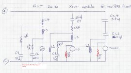
the correct connection for treble filter's inductor
Hi Doug,
I hope that it is an inadvertant error you made in drawing that schematic.
The correct connection point for one end of the .14mH inductor in the treble circuit is between the 3.9uF and 10uF capacitors,
and not between the 10uF cap and the output of the filter.
In the midrange circuit I state here for clarity, moermusic has a 3.3 ohm resistor in the midrange filter.
The Decimal Point is a bit obscured there in his schematic.
I will double check. But as inductor points were never touched, must be a drawing error.
Drawing error. Corrected version below.
Attachments
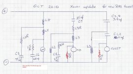
the correct connections
Hi Doug,
now the Schematic is correct,
and thankyou for posting it - it will be of use to some other followers of this thread.
I will state here that the circuit as currently used by moermusic is for listeners whose hearing has diminished somewhat in the highest treble frequencies.
This circuit will not measure as flat response for frequencies higher than the midrange, however it is a valid circuit for any listener who needs some treble prominence, and wants to achieve such with minimal changes to components in the crossover.
I will be posting more about modifications to the crossover for the upper midrange and treble when I get to posting further evaluation of Wayne Swann's nominal circuit, {as posted in #631 on Page 64},
which will not produce coherent listening result regardless to how it may measure on one particular vertical axis,
though I still think the computer was not able to fully incorporate all the necessary information required to caalculate a notionally optimum circuit.
Last edited:
- Status
- This old topic is closed. If you want to reopen this topic, contact a moderator using the "Report Post" button.
- Home
- Loudspeakers
- Multi-Way
- Celestion 66 needs mid-range